
2009 Convert front cig lighters to switch power
 March 3rd, 2013, 4:57 PM
#1

I had a desire to change my cig lighters to only be on when the car was in acc/run, but not off. I have a 2009, and all the power ports are hot all the time. This could be good in some situations but for me it was not so good. Also since there are SO many, I can still plug stuff into a hot port without much trouble by just opening the armrest. This conversion is totally reversible and I didn't cut a single factory wire to do it.
Two reasons I wanted them to shut down.
I took pics of the process and I found a lot of useful links along the way so I wanted to share. This probably applies to many new model year Chevys where they use the Remote Accessory Power circuit, and constant power to the 12V ports. Keep reading for the walk through.
Two reasons I wanted them to shut down.
- I typically have a usb power adapter to charge my phone plugged in all the time, its low profile and is flush with the port so I just leave it. Recently I had the cord dangling onto the floor (which must be common) and being in Minnesota there was some salty slimy water down on my Weathertechs. When I went to plug in my phone later, the end of the cord was totally caked with salt and it had electroplated all the metal of the charger cord and ruined it. The contacts were just gone!!! I know I should not leave the charger/cord plugged in, but I cant be the only person who just leaves it there all the time.
- I also have a Griffin Bluetrip (adds streaming bluetooth) plugged in all the time to the passenger power port with a short cord running up to the aux jack. The bluetrip only works correctly if the cig lighters go on and off with the key. It doesn't reconnect automatically to my phone if the power never cycles. I commute for over an hour each day, and internet radio has saved me from the insanity that is drive time radio commercials.
I took pics of the process and I found a lot of useful links along the way so I wanted to share. This probably applies to many new model year Chevys where they use the Remote Accessory Power circuit, and constant power to the 12V ports. Keep reading for the walk through.
 March 3rd, 2013, 5:53 PM
#2
CF Active Member
I just can't see what the benefit would be here.
And then your post ended after saying to follow along for more?
All you have to do is unplug the stuff....")
And then your post ended after saying to follow along for more?
All you have to do is unplug the stuff....
March 3rd, 2013, 6:00 PM
#3
I thought this project would be fairly easy, I have been tinkering with car stereo and aftermarket addons for years. I have installed a few remote start systems and auto dimming mirrors and am pretty handy with electrical issues.
I got out my multimeter went to work under the dash looking for some switched power. I found quite a few items that were switched when in RUN but not when in ACC. Since I wanted to power my bluetooth, I could see plenty of times when I sit in the car with the radio on, and I didnt want to have to have the key in the RUN position. So next I consulted the almighty Google which lead me to this forum and a few others.
The main thread I found here at chev forum was
https://chevroletforum.com/forum/tah...-2500-a-29570/
In this thread you will find a link to Diesel Place : Chevrolet and GMC Diesel Truck Forums
This thread is worth the registration if you want to add accessories the right way without cutting the factory harness, but I will repeat a few extra things I learned and add one thing I believe is important, a quenching diode.
Here is the bulk of the thread from Diesel place, I hope this is ok to plagiarize, since I posted the link also, and you can't look at this without registering at that forum. I also did all this work on my own as well before I finally registered for that forum when I was working on this write up.
From Diesail:
"There have been many questions as to where to locate RAP (Retained Accessory Power) on the NBS trucks. First let me say thanks to heymccall for all the valuable information that allowed this write-up to happen.
RAP is available to us in the MBEC (Mid-Bussed Electrical Connector) located behind the instrument panel to the left of the brake pedal. The MBEC has 10 positions and the one we are going to us is X14. The problem is that RAP here is limited to only 300 milliamps but there are two other battery feeds in the location as well, one is 15 amps and the other 30. So to use the RAP power for anything but the smallest loads is going to require a relay.
Here are the parts you are going to need and the source that I purchased them from but they are available from many other sources as well.
3 Female GT 280 terminals Delphi Part number 15304711 Mouser part number 829-15304711
1 Relay pigtail Parts express part number 330-075
1 Bosch style relay Parts express part# 330-079
1 GM Connector 20791502 (optional)
Here is the relay harness, relay and connectors.

Click for larger version
If you want to build exactly what he said I suggest you visit his thread linked above. You will have to register.
Bretts Edit: Now you can build exactly what he did here and it will work, but from what I read in the GM upfitters guide here http://www.gmupfitter.com/publicat/2007_BB/09_LD_GMT900_Elec_D3b.pdf (LAST TWO PAGES) YOU MUST ADD A DIODE to protect the BCM.
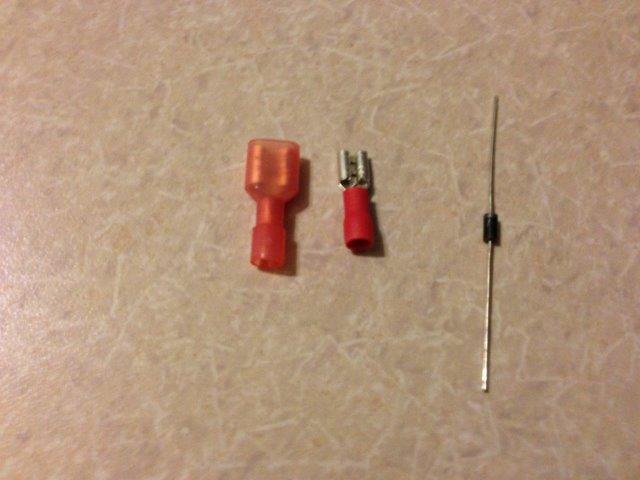
Because of this and the fact that I used a 4 pin SPST relay with a built in fuse, I just made my own pigtail using 18 gauge wire and crimp on insulated connectors. You will need 4 or 5, 1/4 inch females for the relay end, and 3, 1/8 inch female connectors for the MBEC end. I got all the connectors and a diode at radio shack.
I used a 4 pin relay instead of 5 HELLA 003530041 12V/25 Amp SPST Mini ISO Relay with 25 Amp Fuse and Bracket : Amazon.com : Automotive This one is cool because it has a fuse holder built in. Yes there is another one under the hood for this circuit, but this way I can use a smaller fuse than 30 amps from the MBEC for my cig lighters and I don't have to wire a new inline fuse.
This is where you need to add the diode. You can read the article I did to learn about the diode Link To "Relays"... I used a radio shack 1N4007 diode.
Connect the striped end of the diode to terminal 86 on the relay and use this for 12V relay activation (the RAP signal from pin 8). Connect the other end of the diode to terminal 85. Terminal 85 then MUST BE connected to ground via chassis or back to pin 1 in the MBEC or you will fry your diode.
Without the diode 85 and 86 are reversible, but the diode changes that. This is another reason I skipped the pigtail. I just used my wire and the crimp on connectors and when I was crimping on the wires I inserted the thin diode wire with it from the back side.
There are 4-5 connectors on the relay depending on if you have single pole single throw or single pole double throw (SPST or SPDT). Below are the numbers and what they need to be connected to.
Relay trigger positive � relay pin 86 (PIN 8 in MBEC)
Relay trigger ground � relay pin 85 (Any chassis ground, or pin 1 in MBEC)
Constant 12v source � relay pin 30 (for 15 amp Pin 2, for 30 amp Pin 5 MBEC)
Normally Open Contact - relay pin 87 Use this to power your load.
Normally Closed Contact - relay pin 87a, not normally used. This would create a circuit that is ONLY on when the key is OFF. 87a is missing on a 4 pin SPST relay.
Diesail did a nice job with some shrink wrapped wire terminals, I just used some good 3M Super 88 electrical tape. You can actually buy the GM connector but it costs more than the whole job from GM parts direct.
click to view large
I suggest you wire up your relay with about 18 inches of pigtail wire before you start in on your project. When I was done I had three 18 inch wires connected to the relay, with the diode crimped in with two of them, and then three female connectors on the far end waiting to be plugged into the MBEC. Sorry didnt take a photo and its too hard to remove.
After I did that I started to tear apart the burban. First I removed the lower panel under the steering wheel, and the bezel around the radio. The panel has 2 screws and a bolt under the bottom edge. The bolt is under the parking brake release handle. Pull the panel toward the drivers seat to remove.
The bezel around the radio is nerve racking. I used two butter knives to get it off. Look for youtube on it but mostly pry easy. The clips will pop right before you think its going to break. Its really thin and there are 9 very stong clips that are on the inside edge next to the radio and climate controls. and one in the bottom center. I started at the top and slipped on knife in to lift the edge, then insert the second knife as far as it will go toward the radio until it stops, then pry gently, avoid too much deflection of the plastic. If you get the knife up against the pillar the holds the clip it feels ok. No adaquate way to describe the process, even after watching people do it on youtube it was still scary. I have trim panel tools, but the butter knives were just the right mixture of thin and strong. Once its off have a beer, to calm your nerves.
To access the power plugs, remove the two screws on the right and left of the bracket that holds the cig lighters and the power pedal and trac buttons into the dash.
I removed the factory plugs from the back of the two lighters and taped them to the factory harness.
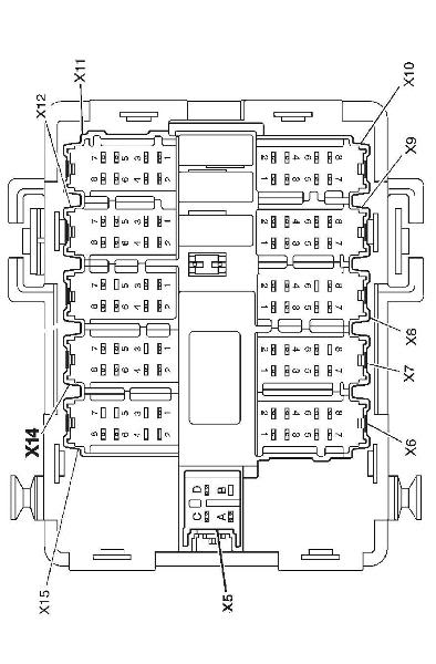
Remove the cover to the MBEC, it looks like this
Click to resize
Here is a diagram of the MBEC connectors; we need to use X14

click to resize
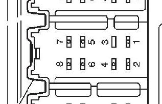
A close-up of X14
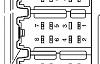
click to resize
Pin 1 - Chassis Ground
Depending on how much power you need, wire pin 2 or 5 to relay lug #30
Pin 2 - B+ ................(15Amp SEO B1 fuse underhood)
Pin 5 - B+ ................(30Amp SEO B2 fuse underhood)
Pin 7 - RUN/CRANK (10Amp SEO/ALC fuse underhood) (not used in this case, can be used without the relay if you just want power when key is in RUN)
Pin 8 - RAP ..............(300Ma from TBC (BCM) to trigger relay, fed by TBC 2B 10Amp in the interior fuse panel) (Wire to pin 86 on relay with striped end of diode to activate circuit when key is in RUN or ACC)
So at this point I started looking for a good place to mount the relay, I settled on right next to the diagnostics port under the dash, I will post pics of this in the next post.
From there I was able to determine that I would need another 3 feet of wire to reach the load and leave some slack for error and wiring at the other end.
I decided to ground my cigs at pin 1 in the MBEC so I didnt have to make any more connections under the dash.
I cut the three feet of extra wire (18 gauge, black and red, two conductor peel apart car stereo typical wire)
I then peeled it apart about 6 inches on one end and terminated the red wire with another quarter inch female insulated spade, and pushed it onto relay pin 87. This will power my cigs.
The remaining black wire which will ground the cigs, I soldered to the black wire that was already connected to pin 85 on the relay. I stripped a gap in the insulation with a sharp knife, I poked the stripped end of the new black wire through the strands of the existing wire and then wrapped them tight around the existing wire strands. After hitting it with some solder, I taped it up good. This way pin 1 is grounding both the relay activation coil and my cigs and I dont have to find a second ground.
So if you can imagine I have a bundle of wire about 4 feet long now, with a relay about a quarter of the way up, two wires, black and red, going one direction for pos and neg to the cig lighters, and three wires going towards the MBEC, red for trigger pos, black for trigger neg, and another red for 12 V constant. The black and red for the trigger were still connected to each other from my role of wire, the second red was peeled from another length of the wire. This was nice so I could keep track of which red was for which purpose and not get confused later. In the other post, Diesail used more colors which would also be a fine idea.
I found a decent path to the area under the radio, its pretty spacious under that dash compared to the toyotas I usually work on. . I used zip ties to hold it, and then routed the wires along side some other bundles that ran into the MBEC, I left them dangle for now.
Then I took the 2 wire end that was now sticking out of my dash under the climate controls and cut it to the length I needed. I stripped about an inch on each end. Then I cut another small maybe 8 inch piece and soldered it to the end of the first. I added the eighth inch crimp ons and pushed them onto the factory lighter lugs which are nicely isolated from each other.
Finally I pushed the lugs on at the MBEC end and tried it out, works great. Now two of my cigs go off with the key. I will post some pics in a reply once I take them. The pics in this post have changed to links somehow and I dont know how to fix that. Sorry I am new to writing with this forum editor thingy.
Brett
Reply with any questions.
I got out my multimeter went to work under the dash looking for some switched power. I found quite a few items that were switched when in RUN but not when in ACC. Since I wanted to power my bluetooth, I could see plenty of times when I sit in the car with the radio on, and I didnt want to have to have the key in the RUN position. So next I consulted the almighty Google which lead me to this forum and a few others.
The main thread I found here at chev forum was
https://chevroletforum.com/forum/tah...-2500-a-29570/
In this thread you will find a link to Diesel Place : Chevrolet and GMC Diesel Truck Forums
This thread is worth the registration if you want to add accessories the right way without cutting the factory harness, but I will repeat a few extra things I learned and add one thing I believe is important, a quenching diode.
Here is the bulk of the thread from Diesel place, I hope this is ok to plagiarize, since I posted the link also, and you can't look at this without registering at that forum. I also did all this work on my own as well before I finally registered for that forum when I was working on this write up.
From Diesail:
"There have been many questions as to where to locate RAP (Retained Accessory Power) on the NBS trucks. First let me say thanks to heymccall for all the valuable information that allowed this write-up to happen.
RAP is available to us in the MBEC (Mid-Bussed Electrical Connector) located behind the instrument panel to the left of the brake pedal. The MBEC has 10 positions and the one we are going to us is X14. The problem is that RAP here is limited to only 300 milliamps but there are two other battery feeds in the location as well, one is 15 amps and the other 30. So to use the RAP power for anything but the smallest loads is going to require a relay.
Here are the parts you are going to need and the source that I purchased them from but they are available from many other sources as well.
3 Female GT 280 terminals Delphi Part number 15304711 Mouser part number 829-15304711
1 Relay pigtail Parts express part number 330-075
1 Bosch style relay Parts express part# 330-079
1 GM Connector 20791502 (optional)
Here is the relay harness, relay and connectors.
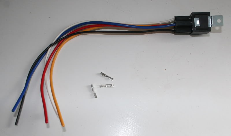
Click for larger version
If you want to build exactly what he said I suggest you visit his thread linked above. You will have to register.
Bretts Edit: Now you can build exactly what he did here and it will work, but from what I read in the GM upfitters guide here http://www.gmupfitter.com/publicat/2007_BB/09_LD_GMT900_Elec_D3b.pdf (LAST TWO PAGES) YOU MUST ADD A DIODE to protect the BCM.
Because of this and the fact that I used a 4 pin SPST relay with a built in fuse, I just made my own pigtail using 18 gauge wire and crimp on insulated connectors. You will need 4 or 5, 1/4 inch females for the relay end, and 3, 1/8 inch female connectors for the MBEC end. I got all the connectors and a diode at radio shack.
I used a 4 pin relay instead of 5 HELLA 003530041 12V/25 Amp SPST Mini ISO Relay with 25 Amp Fuse and Bracket : Amazon.com : Automotive This one is cool because it has a fuse holder built in. Yes there is another one under the hood for this circuit, but this way I can use a smaller fuse than 30 amps from the MBEC for my cig lighters and I don't have to wire a new inline fuse.
This is where you need to add the diode. You can read the article I did to learn about the diode Link To "Relays"... I used a radio shack 1N4007 diode.
Connect the striped end of the diode to terminal 86 on the relay and use this for 12V relay activation (the RAP signal from pin 8). Connect the other end of the diode to terminal 85. Terminal 85 then MUST BE connected to ground via chassis or back to pin 1 in the MBEC or you will fry your diode.
Without the diode 85 and 86 are reversible, but the diode changes that. This is another reason I skipped the pigtail. I just used my wire and the crimp on connectors and when I was crimping on the wires I inserted the thin diode wire with it from the back side.
There are 4-5 connectors on the relay depending on if you have single pole single throw or single pole double throw (SPST or SPDT). Below are the numbers and what they need to be connected to.
Relay trigger positive � relay pin 86 (PIN 8 in MBEC)
Relay trigger ground � relay pin 85 (Any chassis ground, or pin 1 in MBEC)
Constant 12v source � relay pin 30 (for 15 amp Pin 2, for 30 amp Pin 5 MBEC)
Normally Open Contact - relay pin 87 Use this to power your load.
Normally Closed Contact - relay pin 87a, not normally used. This would create a circuit that is ONLY on when the key is OFF. 87a is missing on a 4 pin SPST relay.
Diesail did a nice job with some shrink wrapped wire terminals, I just used some good 3M Super 88 electrical tape. You can actually buy the GM connector but it costs more than the whole job from GM parts direct.

click to view large
I suggest you wire up your relay with about 18 inches of pigtail wire before you start in on your project. When I was done I had three 18 inch wires connected to the relay, with the diode crimped in with two of them, and then three female connectors on the far end waiting to be plugged into the MBEC. Sorry didnt take a photo and its too hard to remove.
After I did that I started to tear apart the burban. First I removed the lower panel under the steering wheel, and the bezel around the radio. The panel has 2 screws and a bolt under the bottom edge. The bolt is under the parking brake release handle. Pull the panel toward the drivers seat to remove.
The bezel around the radio is nerve racking. I used two butter knives to get it off. Look for youtube on it but mostly pry easy. The clips will pop right before you think its going to break. Its really thin and there are 9 very stong clips that are on the inside edge next to the radio and climate controls. and one in the bottom center. I started at the top and slipped on knife in to lift the edge, then insert the second knife as far as it will go toward the radio until it stops, then pry gently, avoid too much deflection of the plastic. If you get the knife up against the pillar the holds the clip it feels ok. No adaquate way to describe the process, even after watching people do it on youtube it was still scary. I have trim panel tools, but the butter knives were just the right mixture of thin and strong. Once its off have a beer, to calm your nerves.
To access the power plugs, remove the two screws on the right and left of the bracket that holds the cig lighters and the power pedal and trac buttons into the dash.
I removed the factory plugs from the back of the two lighters and taped them to the factory harness.
Remove the cover to the MBEC, it looks like this

Click to resize
Here is a diagram of the MBEC connectors; we need to use X14
click to resize
A close-up of X14
click to resize
Pin 1 - Chassis Ground
Depending on how much power you need, wire pin 2 or 5 to relay lug #30
Pin 2 - B+ ................(15Amp SEO B1 fuse underhood)
Pin 5 - B+ ................(30Amp SEO B2 fuse underhood)
Pin 7 - RUN/CRANK (10Amp SEO/ALC fuse underhood) (not used in this case, can be used without the relay if you just want power when key is in RUN)
Pin 8 - RAP ..............(300Ma from TBC (BCM) to trigger relay, fed by TBC 2B 10Amp in the interior fuse panel) (Wire to pin 86 on relay with striped end of diode to activate circuit when key is in RUN or ACC)
So at this point I started looking for a good place to mount the relay, I settled on right next to the diagnostics port under the dash, I will post pics of this in the next post.
From there I was able to determine that I would need another 3 feet of wire to reach the load and leave some slack for error and wiring at the other end.
I decided to ground my cigs at pin 1 in the MBEC so I didnt have to make any more connections under the dash.
I cut the three feet of extra wire (18 gauge, black and red, two conductor peel apart car stereo typical wire)
I then peeled it apart about 6 inches on one end and terminated the red wire with another quarter inch female insulated spade, and pushed it onto relay pin 87. This will power my cigs.
The remaining black wire which will ground the cigs, I soldered to the black wire that was already connected to pin 85 on the relay. I stripped a gap in the insulation with a sharp knife, I poked the stripped end of the new black wire through the strands of the existing wire and then wrapped them tight around the existing wire strands. After hitting it with some solder, I taped it up good. This way pin 1 is grounding both the relay activation coil and my cigs and I dont have to find a second ground.
So if you can imagine I have a bundle of wire about 4 feet long now, with a relay about a quarter of the way up, two wires, black and red, going one direction for pos and neg to the cig lighters, and three wires going towards the MBEC, red for trigger pos, black for trigger neg, and another red for 12 V constant. The black and red for the trigger were still connected to each other from my role of wire, the second red was peeled from another length of the wire. This was nice so I could keep track of which red was for which purpose and not get confused later. In the other post, Diesail used more colors which would also be a fine idea.
I found a decent path to the area under the radio, its pretty spacious under that dash compared to the toyotas I usually work on.
. I used zip ties to hold it, and then routed the wires along side some other bundles that ran into the MBEC, I left them dangle for now.Then I took the 2 wire end that was now sticking out of my dash under the climate controls and cut it to the length I needed. I stripped about an inch on each end. Then I cut another small maybe 8 inch piece and soldered it to the end of the first. I added the eighth inch crimp ons and pushed them onto the factory lighter lugs which are nicely isolated from each other.
Finally I pushed the lugs on at the MBEC end and tried it out, works great. Now two of my cigs go off with the key. I will post some pics in a reply once I take them. The pics in this post have changed to links somehow and I dont know how to fix that. Sorry I am new to writing with this forum editor thingy.
Brett
Reply with any questions.
Last edited by postb8822; March 3rd, 2013 at 8:32 PM. Reason: Work in progress
The following users liked this post:
Mudbeast66 (October 5th, 2023)
March 3rd, 2013, 7:44 PM
#4
Administrator
Be sure whatever ckt you hook into is fused the same as the lighter socket in case someone later decides to plug in a lighter.
I let my cord rest in the gap between dash and the console.
I let my cord rest in the gap between dash and the console.
March 3rd, 2013, 8:13 PM
#5
Since I rewired the whole length of the connection right down to the lugs on the lighters, and used a relay with a fuse holder I can insert the proper fuse, there is a 15 in there now which is more than enough for what I will plug in. I need to check the factory fuse to see what it was, but I know its got heavier wire now then it had before. The weak link is probably the power socked at this point.
Thanks for the reply, I am still working on finishing my write up. I dont see a way to write a draft version so I just keep editing the first post.
March 3rd, 2013, 8:24 PM
#6
Every car I have ever owned, including other GMs have turned off with the key, I stated in my earlier post it was basically to get my bluetooth adapter to work correctly.
Sorry you dont find it useful, but I think others may.
Apologies for the apparent stop in the thread, I also need to learn how to do a draft write up, I was saving it as I went so it was unfinished for awhile, I didn't expect readers to appear so fast, you got there before it was done.
Last edited by postb8822; March 3rd, 2013 at 9:21 PM. Reason: Sounded mean
March 3rd, 2013, 8:58 PM
#7
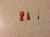
Here are the connectors and the diode 1N4007 I used
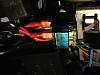
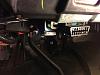
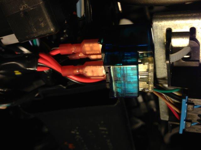
Here is the Relay zipped into place, I was pretty happy as its easy to get to the fuse and not at all visible unless you look under the dash.
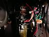
Here is the MBEC before I put the cover back on.
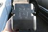
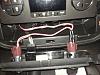
Finally the back side of the cigarette lighters.
I am going to leave that bezel off for awhile to make sure no rattles from anywhere, that was scary to take off. As I said before this is a good way to do what I did, or add any in cabin accessories because its safe for the factory harness and totally reversible.
Thanks for reading.
Brett
Here is the Relay zipped into place, I was pretty happy as its easy to get to the fuse and not at all visible unless you look under the dash.
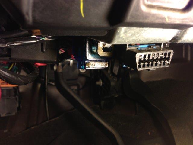
Here is the MBEC before I put the cover back on.

Finally the back side of the cigarette lighters.
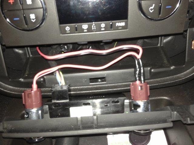
I am going to leave that bezel off for awhile to make sure no rattles from anywhere, that was scary to take off. As I said before this is a good way to do what I did, or add any in cabin accessories because its safe for the factory harness and totally reversible.
Thanks for reading.
Brett
The following users liked this post:
Mudbeast66 (October 5th, 2023)
Trending Topics
March 3rd, 2013, 9:28 PM
#8
Here is the word from GM on the diode
Bulletin No.: 08-08-45-004C
Date: April 08, 2011
Subject: Installation of Electrical Aftermarket Accessories - Battery, Ignition and Ground Feeds - Do Not Splice into Wiring Harness (Install Diode to Solenoid/Relay to Suppress Voltage Spikes)
Models:
2007-2012 Cadillac Escalade, Escalade ESV, Escalade EXT
2007-2012 Chevrolet Avalanche, Silverado, Suburban, Tahoe
2008-2012 Chevrolet Express
2007-2012 GMC Sierra, Sierra Denali, Yukon, Yukon XL, Yukon Denali, Yukon Denali XL
2008-2012 GMC Savana
Supercede:
This bulletin is being revised to add the 2011 and 2012 model years. Please discard Corporate Bulletin Number 08-08-45-004B (Section 08 - Body and Accessories).
Installation of a Diode to Suppress Voltage Spikes
When an electromechanical solenoid or relay is de-energized rapidly by a mechanical switch or semiconductor, the collapsing magnetic field produces a substantial transient voltage in its effort to disperse the stored energy and oppose the sudden change in current flow. These voltage spikes can occur at the positive terminal when the solenoid or relay is de-energized (keyed-off). If a solenoid or relay is wired onto the Run/Crank circuit of the vehicle to control aftermarket equipment, the spikes can be transmitted onto the circuit. The spikes can permanently damage the internal circuitry of the sensitive electronic components and/or control modules that are on this bussed circuit. To prevent damage to these components, the solenoid or relay MUST have the control circuit suppressed with a diode.
The following users liked this post:
Mudbeast66 (October 5th, 2023)
February 1st, 2018, 9:08 AM
#9

I thought this project would be fairly easy, I have been tinkering with car stereo and aftermarket addons for years. I have installed a few remote start systems and auto dimming mirrors and am pretty handy with electrical issues.
I got out my multimeter went to work under the dash looking for some switched power. I found quite a few items that were switched when in RUN but not when in ACC. Since I wanted to power my bluetooth, I could see plenty of times when I sit in the car with the radio on, and I didnt want to have to have the key in the RUN position. So next I consulted the almighty Google which lead me to this forum and a few others.
The main thread I found here at chev forum was
https://chevroletforum.com/forum/tah...-2500-a-29570/
In this thread you will find a link to Diesel Place : Chevrolet and GMC Diesel Truck Forums
This thread is worth the registration if you want to add accessories the right way without cutting the factory harness, but I will repeat a few extra things I learned and add one thing I believe is important, a quenching diode.
Here is the bulk of the thread from Diesel place, I hope this is ok to plagiarize, since I posted the link also, and you can't look at this without registering at that forum. I also did all this work on my own as well before I finally registered for that forum when I was working on this write up.
From Diesail:
"There have been many questions as to where to locate RAP (Retained Accessory Power) on the NBS trucks. First let me say thanks to heymccall for all the valuable information that allowed this write-up to happen.
RAP is available to us in the MBEC (Mid-Bussed Electrical Connector) located behind the instrument panel to the left of the brake pedal. The MBEC has 10 positions and the one we are going to us is X14. The problem is that RAP here is limited to only 300 milliamps but there are two other battery feeds in the location as well, one is 15 amps and the other 30. So to use the RAP power for anything but the smallest loads is going to require a relay.
Here are the parts you are going to need and the source that I purchased them from but they are available from many other sources as well.
3 Female GT 280 terminals Delphi Part number 15304711 Mouser part number 829-15304711
1 Relay pigtail Parts express part number 330-075
1 Bosch style relay Parts express part# 330-079
1 GM Connector 20791502 (optional)
Here is the relay harness, relay and connectors.
Attachment 5190
Click for larger version
If you want to build exactly what he said I suggest you visit his thread linked above. You will have to register.
Bretts Edit: Now you can build exactly what he did here and it will work, but from what I read in the GM upfitters guide here http://www.gmupfitter.com/publicat/2007_BB/09_LD_GMT900_Elec_D3b.pdf (LAST TWO PAGES) YOU MUST ADD A DIODE to protect the BCM.
Because of this and the fact that I used a 4 pin SPST relay with a built in fuse, I just made my own pigtail using 18 gauge wire and crimp on insulated connectors. You will need 4 or 5, 1/4 inch females for the relay end, and 3, 1/8 inch female connectors for the MBEC end. I got all the connectors and a diode at radio shack.
I used a 4 pin relay instead of 5 HELLA 003530041 12V/25 Amp SPST Mini ISO Relay with 25 Amp Fuse and Bracket : Amazon.com : Automotive This one is cool because it has a fuse holder built in. Yes there is another one under the hood for this circuit, but this way I can use a smaller fuse than 30 amps from the MBEC for my cig lighters and I don't have to wire a new inline fuse.
This is where you need to add the diode. You can read the article I did to learn about the diode Link To "Relays"... I used a radio shack 1N4007 diode.
Connect the striped end of the diode to terminal 86 on the relay and use this for 12V relay activation (the RAP signal from pin 8). Connect the other end of the diode to terminal 85. Terminal 85 then MUST BE connected to ground via chassis or back to pin 1 in the MBEC or you will fry your diode.
Without the diode 85 and 86 are reversible, but the diode changes that. This is another reason I skipped the pigtail. I just used my wire and the crimp on connectors and when I was crimping on the wires I inserted the thin diode wire with it from the back side.
There are 4-5 connectors on the relay depending on if you have single pole single throw or single pole double throw (SPST or SPDT). Below are the numbers and what they need to be connected to.
Relay trigger positive � relay pin 86 (PIN 8 in MBEC)
Relay trigger ground � relay pin 85 (Any chassis ground, or pin 1 in MBEC)
Constant 12v source � relay pin 30 (for 15 amp Pin 2, for 30 amp Pin 5 MBEC)
Normally Open Contact - relay pin 87 Use this to power your load.
Normally Closed Contact - relay pin 87a, not normally used. This would create a circuit that is ONLY on when the key is OFF. 87a is missing on a 4 pin SPST relay.
Diesail did a nice job with some shrink wrapped wire terminals, I just used some good 3M Super 88 electrical tape. You can actually buy the GM connector but it costs more than the whole job from GM parts direct.
Attachment 5187
click to view large
I suggest you wire up your relay with about 18 inches of pigtail wire before you start in on your project. When I was done I had three 18 inch wires connected to the relay, with the diode crimped in with two of them, and then three female connectors on the far end waiting to be plugged into the MBEC. Sorry didnt take a photo and its too hard to remove.
After I did that I started to tear apart the burban. First I removed the lower panel under the steering wheel, and the bezel around the radio. The panel has 2 screws and a bolt under the bottom edge. The bolt is under the parking brake release handle. Pull the panel toward the drivers seat to remove.
The bezel around the radio is nerve racking. I used two butter knives to get it off. Look for youtube on it but mostly pry easy. The clips will pop right before you think its going to break. Its really thin and there are 9 very stong clips that are on the inside edge next to the radio and climate controls. and one in the bottom center. I started at the top and slipped on knife in to lift the edge, then insert the second knife as far as it will go toward the radio until it stops, then pry gently, avoid too much deflection of the plastic. If you get the knife up against the pillar the holds the clip it feels ok. No adaquate way to describe the process, even after watching people do it on youtube it was still scary. I have trim panel tools, but the butter knives were just the right mixture of thin and strong. Once its off have a beer, to calm your nerves.
To access the power plugs, remove the two screws on the right and left of the bracket that holds the cig lighters and the power pedal and trac buttons into the dash.
I removed the factory plugs from the back of the two lighters and taped them to the factory harness.
Remove the cover to the MBEC, it looks like this
Attachment 5186
Click to resize
Here is a diagram of the MBEC connectors; we need to use X14
Attachment 5188
click to resize
A close-up of X14
Attachment 5189
click to resize
Pin 1 - Chassis Ground
Depending on how much power you need, wire pin 2 or 5 to relay lug #30
Pin 2 - B+ ................(15Amp SEO B1 fuse underhood)
Pin 5 - B+ ................(30Amp SEO B2 fuse underhood)
Pin 7 - RUN/CRANK (10Amp SEO/ALC fuse underhood) (not used in this case, can be used without the relay if you just want power when key is in RUN)
Pin 8 - RAP ..............(300Ma from TBC (BCM) to trigger relay, fed by TBC 2B 10Amp in the interior fuse panel) (Wire to pin 86 on relay with striped end of diode to activate circuit when key is in RUN or ACC)
So at this point I started looking for a good place to mount the relay, I settled on right next to the diagnostics port under the dash, I will post pics of this in the next post.
From there I was able to determine that I would need another 3 feet of wire to reach the load and leave some slack for error and wiring at the other end.
I decided to ground my cigs at pin 1 in the MBEC so I didnt have to make any more connections under the dash.
I cut the three feet of extra wire (18 gauge, black and red, two conductor peel apart car stereo typical wire)
I then peeled it apart about 6 inches on one end and terminated the red wire with another quarter inch female insulated spade, and pushed it onto relay pin 87. This will power my cigs.
The remaining black wire which will ground the cigs, I soldered to the black wire that was already connected to pin 85 on the relay. I stripped a gap in the insulation with a sharp knife, I poked the stripped end of the new black wire through the strands of the existing wire and then wrapped them tight around the existing wire strands. After hitting it with some solder, I taped it up good. This way pin 1 is grounding both the relay activation coil and my cigs and I dont have to find a second ground.
So if you can imagine I have a bundle of wire about 4 feet long now, with a relay about a quarter of the way up, two wires, black and red, going one direction for pos and neg to the cig lighters, and three wires going towards the MBEC, red for trigger pos, black for trigger neg, and another red for 12 V constant. The black and red for the trigger were still connected to each other from my role of wire, the second red was peeled from another length of the wire. This was nice so I could keep track of which red was for which purpose and not get confused later. In the other post, Diesail used more colors which would also be a fine idea.
I found a decent path to the area under the radio, its pretty spacious under that dash compared to the toyotas I usually work on.. I used zip ties to hold it, and then routed the wires along side some other bundles that ran into the MBEC, I left them dangle for now.
Then I took the 2 wire end that was now sticking out of my dash under the climate controls and cut it to the length I needed. I stripped about an inch on each end. Then I cut another small maybe 8 inch piece and soldered it to the end of the first. I added the eighth inch crimp ons and pushed them onto the factory lighter lugs which are nicely isolated from each other.
Finally I pushed the lugs on at the MBEC end and tried it out, works great. Now two of my cigs go off with the key. I will post some pics in a reply once I take them. The pics in this post have changed to links somehow and I dont know how to fix that. Sorry I am new to writing with this forum editor thingy.
Brett
Reply with any questions.
I got out my multimeter went to work under the dash looking for some switched power. I found quite a few items that were switched when in RUN but not when in ACC. Since I wanted to power my bluetooth, I could see plenty of times when I sit in the car with the radio on, and I didnt want to have to have the key in the RUN position. So next I consulted the almighty Google which lead me to this forum and a few others.
The main thread I found here at chev forum was
https://chevroletforum.com/forum/tah...-2500-a-29570/
In this thread you will find a link to Diesel Place : Chevrolet and GMC Diesel Truck Forums
This thread is worth the registration if you want to add accessories the right way without cutting the factory harness, but I will repeat a few extra things I learned and add one thing I believe is important, a quenching diode.
Here is the bulk of the thread from Diesel place, I hope this is ok to plagiarize, since I posted the link also, and you can't look at this without registering at that forum. I also did all this work on my own as well before I finally registered for that forum when I was working on this write up.
From Diesail:
"There have been many questions as to where to locate RAP (Retained Accessory Power) on the NBS trucks. First let me say thanks to heymccall for all the valuable information that allowed this write-up to happen.
RAP is available to us in the MBEC (Mid-Bussed Electrical Connector) located behind the instrument panel to the left of the brake pedal. The MBEC has 10 positions and the one we are going to us is X14. The problem is that RAP here is limited to only 300 milliamps but there are two other battery feeds in the location as well, one is 15 amps and the other 30. So to use the RAP power for anything but the smallest loads is going to require a relay.
Here are the parts you are going to need and the source that I purchased them from but they are available from many other sources as well.
3 Female GT 280 terminals Delphi Part number 15304711 Mouser part number 829-15304711
1 Relay pigtail Parts express part number 330-075
1 Bosch style relay Parts express part# 330-079
1 GM Connector 20791502 (optional)
Here is the relay harness, relay and connectors.
Attachment 5190
Click for larger version
If you want to build exactly what he said I suggest you visit his thread linked above. You will have to register.
Bretts Edit: Now you can build exactly what he did here and it will work, but from what I read in the GM upfitters guide here http://www.gmupfitter.com/publicat/2007_BB/09_LD_GMT900_Elec_D3b.pdf (LAST TWO PAGES) YOU MUST ADD A DIODE to protect the BCM.
Because of this and the fact that I used a 4 pin SPST relay with a built in fuse, I just made my own pigtail using 18 gauge wire and crimp on insulated connectors. You will need 4 or 5, 1/4 inch females for the relay end, and 3, 1/8 inch female connectors for the MBEC end. I got all the connectors and a diode at radio shack.
I used a 4 pin relay instead of 5 HELLA 003530041 12V/25 Amp SPST Mini ISO Relay with 25 Amp Fuse and Bracket : Amazon.com : Automotive This one is cool because it has a fuse holder built in. Yes there is another one under the hood for this circuit, but this way I can use a smaller fuse than 30 amps from the MBEC for my cig lighters and I don't have to wire a new inline fuse.
This is where you need to add the diode. You can read the article I did to learn about the diode Link To "Relays"... I used a radio shack 1N4007 diode.
Connect the striped end of the diode to terminal 86 on the relay and use this for 12V relay activation (the RAP signal from pin 8). Connect the other end of the diode to terminal 85. Terminal 85 then MUST BE connected to ground via chassis or back to pin 1 in the MBEC or you will fry your diode.
Without the diode 85 and 86 are reversible, but the diode changes that. This is another reason I skipped the pigtail. I just used my wire and the crimp on connectors and when I was crimping on the wires I inserted the thin diode wire with it from the back side.
There are 4-5 connectors on the relay depending on if you have single pole single throw or single pole double throw (SPST or SPDT). Below are the numbers and what they need to be connected to.
Relay trigger positive � relay pin 86 (PIN 8 in MBEC)
Relay trigger ground � relay pin 85 (Any chassis ground, or pin 1 in MBEC)
Constant 12v source � relay pin 30 (for 15 amp Pin 2, for 30 amp Pin 5 MBEC)
Normally Open Contact - relay pin 87 Use this to power your load.
Normally Closed Contact - relay pin 87a, not normally used. This would create a circuit that is ONLY on when the key is OFF. 87a is missing on a 4 pin SPST relay.
Diesail did a nice job with some shrink wrapped wire terminals, I just used some good 3M Super 88 electrical tape. You can actually buy the GM connector but it costs more than the whole job from GM parts direct.
Attachment 5187
click to view large
I suggest you wire up your relay with about 18 inches of pigtail wire before you start in on your project. When I was done I had three 18 inch wires connected to the relay, with the diode crimped in with two of them, and then three female connectors on the far end waiting to be plugged into the MBEC. Sorry didnt take a photo and its too hard to remove.
After I did that I started to tear apart the burban. First I removed the lower panel under the steering wheel, and the bezel around the radio. The panel has 2 screws and a bolt under the bottom edge. The bolt is under the parking brake release handle. Pull the panel toward the drivers seat to remove.
The bezel around the radio is nerve racking. I used two butter knives to get it off. Look for youtube on it but mostly pry easy. The clips will pop right before you think its going to break. Its really thin and there are 9 very stong clips that are on the inside edge next to the radio and climate controls. and one in the bottom center. I started at the top and slipped on knife in to lift the edge, then insert the second knife as far as it will go toward the radio until it stops, then pry gently, avoid too much deflection of the plastic. If you get the knife up against the pillar the holds the clip it feels ok. No adaquate way to describe the process, even after watching people do it on youtube it was still scary. I have trim panel tools, but the butter knives were just the right mixture of thin and strong. Once its off have a beer, to calm your nerves.
To access the power plugs, remove the two screws on the right and left of the bracket that holds the cig lighters and the power pedal and trac buttons into the dash.
I removed the factory plugs from the back of the two lighters and taped them to the factory harness.
Remove the cover to the MBEC, it looks like this
Attachment 5186
Click to resize
Here is a diagram of the MBEC connectors; we need to use X14
Attachment 5188
click to resize
A close-up of X14
Attachment 5189
click to resize
Pin 1 - Chassis Ground
Depending on how much power you need, wire pin 2 or 5 to relay lug #30
Pin 2 - B+ ................(15Amp SEO B1 fuse underhood)
Pin 5 - B+ ................(30Amp SEO B2 fuse underhood)
Pin 7 - RUN/CRANK (10Amp SEO/ALC fuse underhood) (not used in this case, can be used without the relay if you just want power when key is in RUN)
Pin 8 - RAP ..............(300Ma from TBC (BCM) to trigger relay, fed by TBC 2B 10Amp in the interior fuse panel) (Wire to pin 86 on relay with striped end of diode to activate circuit when key is in RUN or ACC)
So at this point I started looking for a good place to mount the relay, I settled on right next to the diagnostics port under the dash, I will post pics of this in the next post.
From there I was able to determine that I would need another 3 feet of wire to reach the load and leave some slack for error and wiring at the other end.
I decided to ground my cigs at pin 1 in the MBEC so I didnt have to make any more connections under the dash.
I cut the three feet of extra wire (18 gauge, black and red, two conductor peel apart car stereo typical wire)
I then peeled it apart about 6 inches on one end and terminated the red wire with another quarter inch female insulated spade, and pushed it onto relay pin 87. This will power my cigs.
The remaining black wire which will ground the cigs, I soldered to the black wire that was already connected to pin 85 on the relay. I stripped a gap in the insulation with a sharp knife, I poked the stripped end of the new black wire through the strands of the existing wire and then wrapped them tight around the existing wire strands. After hitting it with some solder, I taped it up good. This way pin 1 is grounding both the relay activation coil and my cigs and I dont have to find a second ground.
So if you can imagine I have a bundle of wire about 4 feet long now, with a relay about a quarter of the way up, two wires, black and red, going one direction for pos and neg to the cig lighters, and three wires going towards the MBEC, red for trigger pos, black for trigger neg, and another red for 12 V constant. The black and red for the trigger were still connected to each other from my role of wire, the second red was peeled from another length of the wire. This was nice so I could keep track of which red was for which purpose and not get confused later. In the other post, Diesail used more colors which would also be a fine idea.
I found a decent path to the area under the radio, its pretty spacious under that dash compared to the toyotas I usually work on.
. I used zip ties to hold it, and then routed the wires along side some other bundles that ran into the MBEC, I left them dangle for now.Then I took the 2 wire end that was now sticking out of my dash under the climate controls and cut it to the length I needed. I stripped about an inch on each end. Then I cut another small maybe 8 inch piece and soldered it to the end of the first. I added the eighth inch crimp ons and pushed them onto the factory lighter lugs which are nicely isolated from each other.
Finally I pushed the lugs on at the MBEC end and tried it out, works great. Now two of my cigs go off with the key. I will post some pics in a reply once I take them. The pics in this post have changed to links somehow and I dont know how to fix that. Sorry I am new to writing with this forum editor thingy.
Brett
Reply with any questions.

So does this diagram look correct? I am concerned about the diode direction. I know that 85 and 86 isn't in there normal positions on a relay but it was easier to change the numbers around. Thanks
The following users liked this post:
Mudbeast66 (October 5th, 2023)
