Chevrolet Silverado 1999-2013: Why is My Instrument Cluster Broken?
The instrument cluster transmits most of truck's functions to the driver. This is done by illuminating warning lights, displaying a message on the center digital display screen, and moving needles associated with speed and engine revolutions. The cluster contains a series of electronics that communicate with vehicle modules to correctly display these readings.
This article applies to the Chevrolet Silverado GMT800 and GMT900 (1999-2013).
The cluster is the main source of information on the truck's status for the driver. Inside the cluster are many electronic components and motors working to keep the cluster operating normally. These small electronic components are soldered together on circuit boards. Circuit boards are very fragile that can become damaged from heat and vibration. Motors working the gauges are tasked with constant movement while the truck is running, and a failure is commonly seen as erratic needle movement. The cluster also houses bulbs that illuminate warning lights, such as the anti-lock braking system and check engine light.
Materials Needed
- Screwdriver set
- Socket set
- Digital multimeter
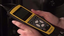
- Scan tool with data viewing
Step 1 – Perform an instrument cluster test
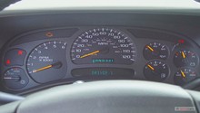
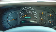
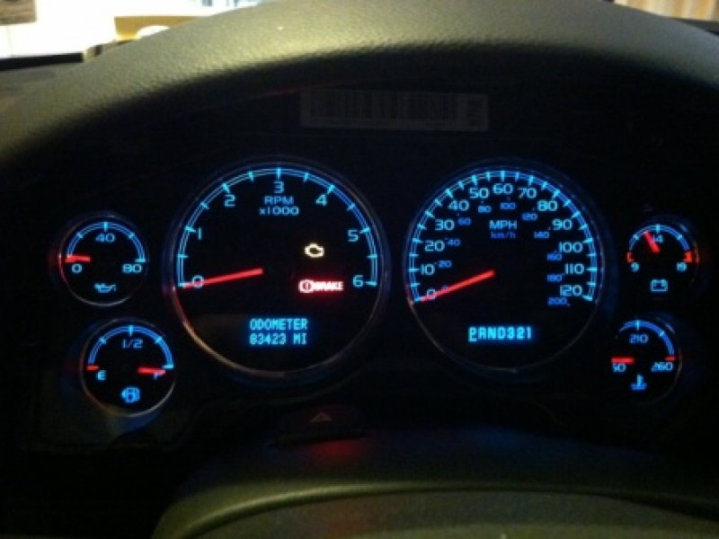
This test will verify what on the cluster is working and what is not. Simply turn the key to the "on" position and watch for all the warning lights to illuminate. Some Silverados may perform a "needle sweep," which moves all the gauge needles from right to the left. A standard opening message should also be viewed from the digital display on the cluster, indicating no codes are present relating the cluster's functions.
Step 2 – Diagnose the cause of the cluster problem
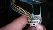
If you find a needle on your cluster is not functioning normally, there could be several problems. The cluster may contain the problem—or in the case of the gauges' monitoring engine related functions—of a defective sensor or wiring. The best way to go about this type of problem is to analyze the correct wiring diagram for the related circuit, and check for the correct voltage levels at the proper terminals (typically the power and ground). If these check out, your problem lies with the motors controlling the gauges. Some scan tools with factory level data monitoring can view these voltage levels.
If you find a warning light that will not illuminate, you will need to disassemble the cluster and replace the bulb with the correct part number. You may find multiple lights or areas of the cluster indicating more than one bulb could be blown, or a problem with the cluster itself.
If you find your digital display screens not fully displaying a message (dots appear to be missing), the display has been damaged and you will need a replacement. A power and ground issue can cause the display to appear dim or appear to be flickering. Verifying the correct power and ground levels are reaching the cluster will ensure your wiring is not the problem. The cluster will need close to 12 volts at the power wire, and less than one-hundred milli-volts on the ground wire.

Figure 2. Removing the trim cover over the instrument cluster. 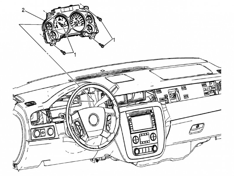
Figure 3. Removing the instrument cluster from the dashboard. 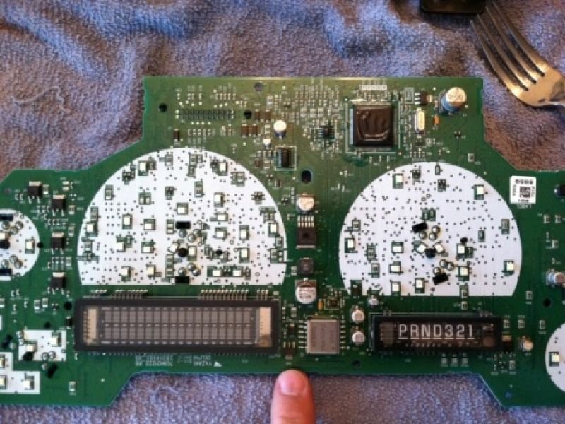
Figure 4. The instrument cluster circuit board.
Step 3 – Your truck may need a software update
Software updates are periodically made to refine and calibrate the modules operations. Some examples of what an update can do for the instrument cluster are changing the procedure for the cluster power-up test, or the current levels that reach the cluster.
Your truck will need to be taken to a dealer or independent shop that has access to a factory level compatible scan tool to perform this update.
Related Discussions
- Tahoe/Suburban Instrument Cluster Repair - ChevroletForum.com
- Silverado Instrument Cluster - ChevroletForum.com
- Instrument Cluster Problems - ChevroletForum.com
- Gauges Going Nuts - ChevroletForum.com