Chevrolet Silverado 2007-2013: How to Lower Your Truck
Lowering kits enhance the style, and in some cases the performance of your truck. Installation is not always easy because some kits require modification to the frame. But if you are interested in taking on the task, this article will guide you through the process.
This article applies to the Chevrolet Silverado GMT900 (2007-2013).
Lowering kits come in a wide array of sizes from one to two inches all the way to five and six inches. Commonly found lowering kit components include drop spindles, coil springs, torsion keys, flip kits, and shackle hangers. Kits with a large amount of drop will benefit from specifically designed shocks to maintain ride comfort. Lowering kits can enhance your Silverado's performance by lowering its center of gravity and maintaining tire contact with the road through the use of stiffer springs.
(Related Article: Lowering Modifications - ChevroletForum.com)

Materials Needed
- Socket set (10mm-22mm)
- 1/2" ratchet
- 1/2" extensions
- Wrench set
- Hammer
- Impact wrench (air or electric)
- Breaker bar
- Pry bar
- Spring compressor
- Electric or air powered saw
- Electric or air powered drill
- Cut-off wheel
- Vice grip pliers
- Tie rod puller or pickle fork
- Ball joint removal tool
- Hammer (optional)
- Floor jack
- Jack stands
- Safety glasses
Step 1 – Raise the truck and remove the wheels
Set the emergency brake. If you are not using an air or electric powered impact wrench, loosen your lug nuts with the wheels on the ground. The lug nuts are 22mm.
Ready your jack stands beside the truck and use your floor jack to raise one corner at a time, positioning a jack stand at each corner below the frame rail. You can use blocks of wood to increase the raised height and decrease the chance of damage from the jack stands.

(Related Article: How to Jack Up Your Truck - ChevroletForum.com)
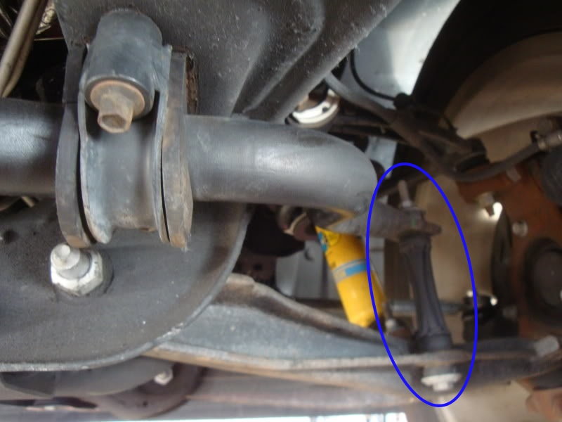
Step 2 – Remove the sway bar end links
Remove the end links by using a wrench to hold the nut on the top of the end link in place. Then use a socket to rotate the bolt on the bottom side counterclockwise.
Step 3 – Remove the coil springs and/or strut assemblies
For those changing their shocks and/or strut assemblies, begin removing the strut by loosening the three 18mm nuts holding the top of the strut in place. One nut has a clip over it attached to a wiring harness. Remove the clip by lifting it off the nut. Now remove the two bolts securing the bottom of the strut with a 15mm socket. Afterwards, the strut can be wiggled down and out of the truck.
To remove the coil spring from the strut assembly, use a spring compression tool. After the spring is compressed, loosen the center nut at the top of the strut and hold the shaft in place with a pair of vice grip pliers. Refer to your kit's specific instructions for the exact procedure during this step.
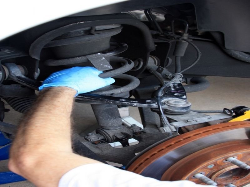
Figure 3. Removing the strut assembly. 
Figure 4. Compressing the coil springs.
Step 4 – Remove the tie rods from the spindles
The tie rods have tapered ends that are secured to the spindle by nuts. Once these nuts are removed, you will need to use either a tie rod puller or pickle fork to unseat the tie rod from the spindle. It is easy to accidentally tear the rubber boot on the end of the tie rod with a pickle fork.
You can also strike the spindle (only use this method with non-aluminum spindles) with a hammer near the tie rod. The resulting jolt can sometimes be enough to dislodge the tie rod.
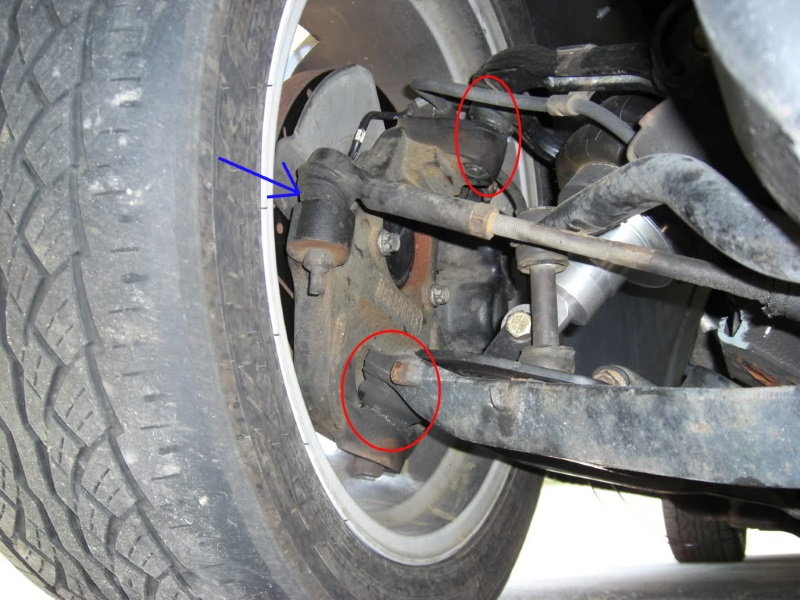
Figure 5. Insert the pickle fork between the tie rod end and spindle (blue arrow). Disregard the red circles until the next step. 
Figure 6. The tie rod has been removed from the spindle.
Step 5 – Separate the upper and lower ball joints from the spindle
As seen in Figure 6, the ball joints have tapered ends that slide through the spindle and are held in place by a nut.
Like the tie rod removal, a ball joint removal tool is made that reduces the risk of damaging the ball joint. If you do not have access to one, you can use a pickle fork; although, this may tear the ball joint rubber boot. A swift strike from a hammer against the spindle near the ball joints is sometimes enough to brake them free. Do not use the hammer method with aluminum spindles.

Step 6 – Install the drop spindles and strut assemblies
Your new drop spindles will slide right into place onto the ball joints between the control arms. Tighten the ball joint nuts down, and then install the tie rod ends in the same fashion.
You are now ready to re-install the struts. Slide them into position and start the three 18mm nuts at the top. Then, tighten the bottom of the strut to the lower control arm with the two 15mm bolts. Re-attach your sway bar end links to the sway bar and lower control arm.
Step 7 – Remove the rear shocks
Now that the front is finished, begin the rear installation by supporting the rear axle. This should be done with jack stands, but you will need to keep you floor jack close by.
Remove the rear shocks by loosening the two 21mm bolts at the top and bottom of the shock. The bottom bolt will require using a wrench to keep the nut from spinning in place.
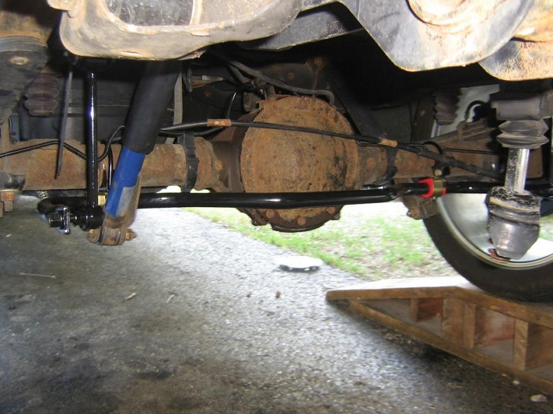
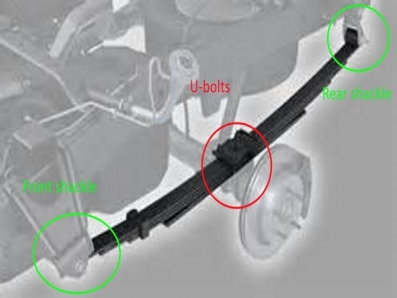
Step 8 – Remove the leaf springs
Two U-bolts secured by nuts hold the leaf springs to the rear axle. The leaf spring itself is held onto mounts attached to the frame rail by one bolt at each end.
Step 9 – Install the new leaf spring mounts and leaf spring shackles
The new leaf spring mounts will surround the rear axle from the bottom, and the leaf springs will be secured to the bottom of the mounts by the U-bolts. The adjustable spring shackles will mount in place of the originals. Some lowering kits will include new shackle hangers. The original shackle hangers are riveted to the frame. The rivets will need to be grinded off of the hangers for removal.

Step 10 – Install the rear axle flip kit
For axle flips kits that allow larger drops (usually greater than four inches), you will need to notch the frame rails. This will require cutting and drilling. Remove any brake lines and sections of wiring from the frame in the area where you will be cutting and drilling.
Use the flip kit plate included in your kit to trace the area on the frame rail you will need to remove. Cut the frame rail using a cut-off wheel and electric saw. Drill new holes into the frame that correspond to the same size as the bolts you will be using to secure the notch plate to the frame.
The rear axle can now be lifted into position, and the leaf spring can be tightened into place at the shackles and U-bolts.
Install the new extended rear shocks.
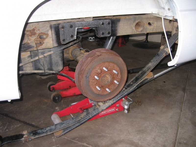
Figure 11. The notch has been cut from the frame and the plate bolted in place.
Step 11 – Finish the installation
Be sure you have correctly tightened all include hardware. Look for areas that may come into contact with a component. Move the front spindles side to side in there full range of motion to ensure there is adequate clearance.
Attach the wheels and slowly lower the truck, making sure there is proper clearance. Turn the steering wheel left to right again, listening for any clunks or scrapes. Metal to metal sound is a indicator something may be bent or incorrectly installed. Finally, perform a test drive to verify everything is in proper working order.

Featured Video: How to Lower Your Truck
Related Discussions
- How to Lower My Truck - ChevroletForum.com
- Question on Lowering Rear - ChevroletForum.com
- Rough Start on Lowered Silverado - ChevroletForum.com
- Lowering My Silverado - ChevroletForum.com