Chevrolet Silverado 2007-2013: How to Replace Upper Control Arm
Is your truck pulling way too much in one direction? Maybe it's not just an alignment issue, but something more. Here is how to correctly replace a control arm.
This article applies to the Chevrolet Silverado GMT900 (2007-2013).
Your Chevy Silverado isn't much without a proper working suspension system, and a damaged control arm leaves the affected side vulnerable to transferring all types of vibrations to the cabin, distorting the wheel alignment and wearing down those large, expensive tires way too fast. The control arm is vital in creating a stable ride for your truck and should not be overlooked. Before you complete the replacement procedure, make sure to have an alignment appointment ready. The following instructions detail how to replace a damaged control arm on your Chevy Silverado.

Materials Needed
- Metric socket set (up to 22mm)
- Jack and jack stands
- 20-inch extension
- Breaker bar
- Hammer
- Torque wrench
Step 1 – Break loose the lug nuts and raise the truck
- While the truck is on the ground, break loose the lug nuts.
- Use a jack to safely lift the truck.
- Rest the chassis on the jack stands.
- Finish removing the lug nuts and wheel.

(Related Article: How to Jack Up Your Truck - ChevroletForum.com)
Step 2 – Locate the strut tower bolts
The control arm bolts are in-between the control arm and shock tower, so the strut will need to be removed.
- Locate the strut tower bolts inside the engine bay.
- Remove the wire clipped onto the strut tower bolts.
- Use an 18mm socket with an extension to loosen the three bolts.

Figure 2. Locate the strut tower nuts. 
Figure 3. Use an 18mm socket to loosen the strut tower nuts.
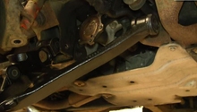
Step 3 – Begin removing suspension components
- Begin by pulling the hub assembly outwards, so all the suspension components can easily be accessed.
- Loosen the stabilizer link nuts by placing a wrench on top and a socket on the bottom.
- Remove the two 15mm bolts that hold the strut tower in place from the lower control arm.
- Remove the strut tower assembly.

Figure 4. Remove the stabilizer link nuts. 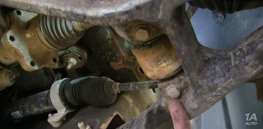
Figure 5. Remove the two 15mm strut tower bolts. 
Figure 6. Remove the strut tower assembly.
Step 4 – Remove the control arm
Before loosening any of the nuts, you need to mark off the control arm's position. Doing so allows you to install the control arm as close to straight as possible; however, the truck will still need a complete alignment after the installation is complete. Doing this will at least make it safely driveable to take a trip to your local alignment shop.

- Loosen the 18mm locking nut on the control arm ball joint, but do not completely remove it.
- Use a pry bar to pop the ball joint off of the hub assembly.
-
Remove the 10mm nut holding the wire harness to the control arm.

Figure 8. Loosen the 18mm locking nut. 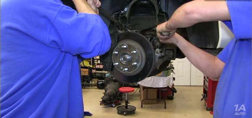
Figure 9. Pry the control arm off. 
Figure 10. Remove the 10mm bolt for the wire harness.
- Loosen the control arm nuts on both sides.
- Hammer out the control arm bolts.
-
Use a pry bar to remove the control arm from the chassis.

Figure 11. Loosen the control arm bolts. 
Figure 12. Hammer out the control arm bolts. 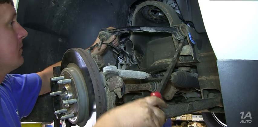
Figure 13. Pry out the control arm.
Step 5 – Install the new control arm
- Install the new control arm.
- Adjust the control arm alignment to the marked area.
- Tighten the control arm to 100 ft./lbs.
- Mount the control arm ball joint to the hub assembly.
- Use a Allen key to hold the ball joint stud in place and tighten it.

Figure 14. Mount the control arm. 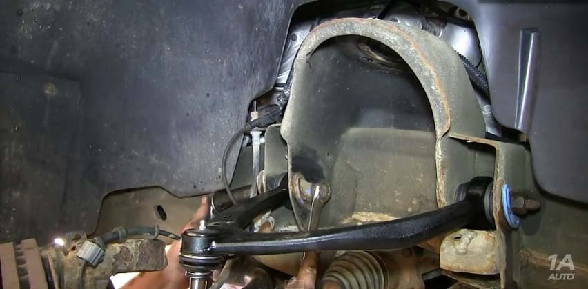
Figure 15. Tighten the control arm in place. 
Figure 16. Install the control arm ball joint into the hub assembly. 
Figure 17. Tighten the ball joint to the hub assembly.
- Proceed to install the strut assembly along with the stabilizer link, and mount the wheel.
- Hand-tighten the lug nuts and use the 18mm socket to finish mounting the strut tower to the chassis.
- Lower the car and finish torquing down the lug nuts on the wheel.

Featured Video: How to Install Front Upper Control Arm
Related Discussions
- Upper Control Arm - ChevroletForum.com
- Upper Control Arm Bushings - ChevroletForum.com
- Urethane Control Arm Bushings - ChevroletForum.com