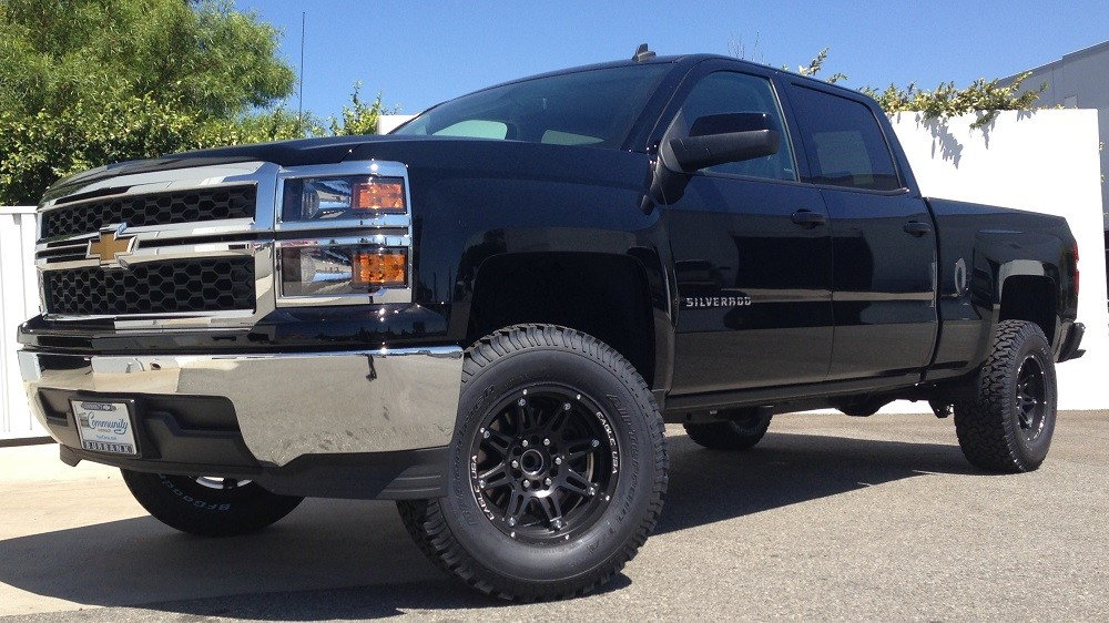
Chevrolet Silverado 2014-Present: How to Install a Lift Kit
Suspension lift kits for a Chevy Silverado 1500 are made of many large, high-strength components. Proper installation requires not only brawn, but finesse and an understanding of the correct procedures.
This article applies to the Chevrolet Silverado 1500 (2014-present).
Lift kits for the Chevrolet Silverado 1500 are made by many manufacturers. How high you decide to go will determine what needs to be removed/installed. The installation is not easy, requiring removal of major suspension components and in some instances, modification to factory parts. It is crucial that care is taken when removing and installing each component as a bend or twist in the wrong area can lead to alignment problems, making your truck difficult to control.

Materials Needed
- Safety glasses
- Jackstands
- Floor jack/ block a wood
- Measuring tape
- Strut spring compressor (may not need this depending on your kit)
- Standard and metric wrenches/sockets
- Allen wrenches
- Torque wrench
- Hammer
- Wheel blocks
- Screwdrivers
- Transmission jack
If your kit involves fabrication you will also need:
- Welder
- Reciprocating saw
- Grinder
Step 1 – Raise/hoist the vehicle
- Set the emergency brake and block the rear wheels.
- If you do not have an air or electric impact wrench, loosen the front wheels before raising them.
- Raise the front of the truck by positioning the floor jack and block of wood underneath the crossmember.
- Place jack stands on each frame rail behind the front wheel wells.
- Carefully lower the floor jack onto the jack stands.
Step 2 – Remove the front wheels
- Using a 22mm socket, remove the front wheels.
- Your wheel may have a center cap. Look for an indented area around the outside of the cap and use a screwdriver to pry the cap off the wheel.
- Once the wheel is off, you will see a brake line routed on the upper control arms. Remove it from the bracket.
Step 3 – Remove the tie rods from the steering knuckles
- Using an 18mm socket, remove the nuts holding the tie rods to the spindles.
- Once removed, you can use your hammer and strike the knuckle near the tie rod to unseat it.
- Do not do this if your truck has aluminum steering knuckles. Instead, you can gently hit the end of the tie rod. A tie rod puller or pickle fork can also be used.

Step 4 – Remove the front brake calipers
- There are two bolts holding the brake calipers to the rotors. Remove them and wire the caliper to the frame.
- Do not let the caliper hang by the brake hose.
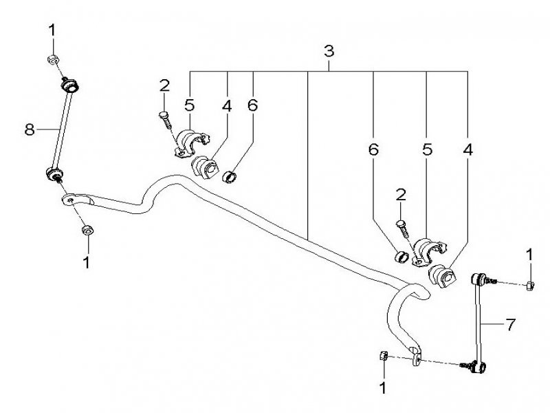
Step 5 – Remove the front sway bar
- Use a 15mm socket to remove the sway bar end links from the sway bar and lower control arm.
- There are also 4 bolts holding the sway bar to the frame surrounded by caps.
Step 6 – Remove the front strut assemblies
- Begin removal by positioning your floor jack under the lower control arm.
- You will need to support the control arm once the strut has been removed.
- Remove the lower strut mounting bolts, then the upper strut retaining nuts.
Warning
DO NOT remove the center strut rod nut. It is under extreme pressure.
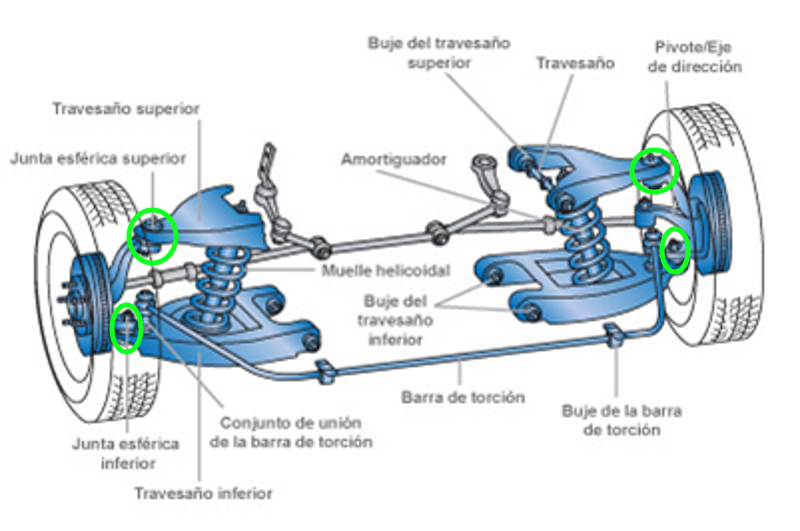
Step 7 – Disconnect the control arms from the spindle
- The control arms are held to the spindle by upper and lower ball joints.
- These ball joints can be removed from the spindle by striking the spindle with a hammer (similar to tie rod removal) if your spindle is steel.
- Owners with aluminum spindles can remove their ball joints by using a pickle fork or pry bar. A ball joint removal tool is made to make this easier.
Step 8 – Remove the CV axles, lower control arms, and rear crossmember
- Removal of the CV axles is done by loosening the six bolts with a 15mm socket holding them to the differential.
- If you have not already removed the front skid plate, remove it now by loosening the bolts with a 15mm socket.
- The lower control arms are held in place by bolts that require 18mm and 24mm sockets.
- Remove the rear crossmember by loosening four 18mm bolts holding it on the truck.

Step 9 – Remove the rack-and-pinion (optional)
- This step is not required with all kits.
- First, disconnect the steering shaft and any electrical connectors from the rack.
- Remove the bolts with both 18mm and 24mm sockets holding the rack to the truck.

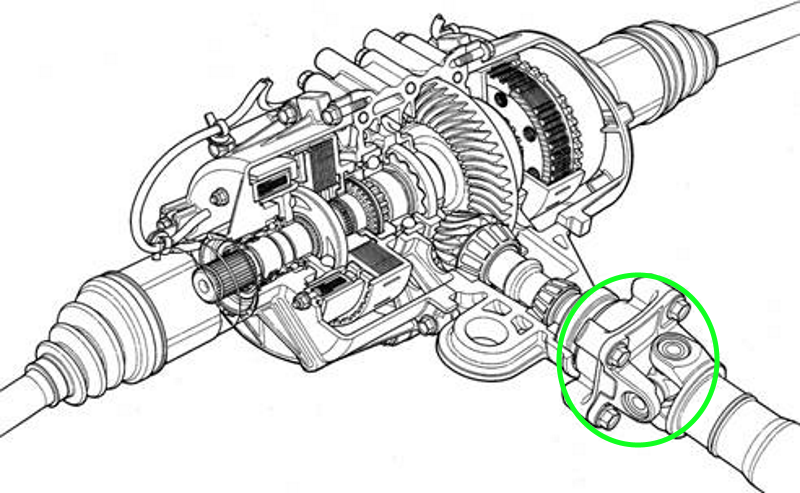
Step 10 – Remove the front differential
- Remove the driveshaft from the front differential.
- Support the front differential with a transmission jack.
- Then remove the two differential mounting bolts on the drivers side and the two nuts on the passenger side using 15mm and 18mm sockets.
After this step, some fabrication and modification will be required depending on which kit you decide to buy. Each kit has unique components, but most include new spindles, differential relocation, crossmembers, and front struts or strut spacers. Remember to correctly torque each component. Once completed, lower the front back down and prepare to begin the rear installation.
Step 11 – Raise and support the rear of the truck, and remove the rear wheels
- Place the wheel blocks in front of the front wheels, and raise the rear of the truck.
- Place jack stands on the frame rails just ahead of the front leaf spring frame mount.
- Using a 22mm socket, remove the rear wheels.
Step 12 – Remove the rear shocks and u-bolts
- Using your floor jack, support the rear differential.
- Routed along the differential and axle are brackets that hold the brake lines in position. They are located at the top of the differential as well as the bottom and top of the frame rails.
- Remove the parking brake cable bracket from the top of the driver's side frame rail.
- Now remove the rear shocks and u-bolts. The rear shocks will be held in place by bolts at the top and bottom of the shock.

Step 13 – Install the new lift blocks and shocks
Depending on your kit, you may or may not re-use the factory lift blocks.
- Carefully lower the rear axle down to gain access to the lift blocks. Remove them if required. Make sure you do not over-extend any break lines.
- Position the new lift blocks between the axle and spring taking note of any special orientation.
- Install the u-bolts, and rear shocks once the axle is raised back up, and re-attach the brake lines.
Step 14 – Finish the installation
- Mount and tighten the wheels back onto the hub. Wheels are torqued from 100-140 ft lbs depending on your particular wheel.
- Once the vehicle is lowered to the ground, look around and under the truck for any loose or missing parts. Make sure their are proper clearances between components.
- Turn the wheel from stop to stop to ensure your wheels/tires have the proper clearance.
Related Sites
- Lift Kit Installation - Skyjacker.com
- Installation PDF - 4X4media.info
- Suspension Instructions - Bds-suspension.com