
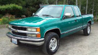
DIY/Walkthrough for VCM/ECU ground wire update
 February 2nd, 2011, 10:50 AM
#1

I would first like to say I hold No responsibility for any damages or problems that may happen following this thread. This is simply a helpful guide with pictures Ideas and extra Information on performing the VCM ground wire update. If you have any questions or if your not sure Please do not attempt as this could blow your ECU.
Now the 1st step is to disconnected the Neg Battery terminal. Once done Locate your ECU it will have 4 large plugs and 2 smaller ones.
The top Left Plug Will say White, Grey or Clear.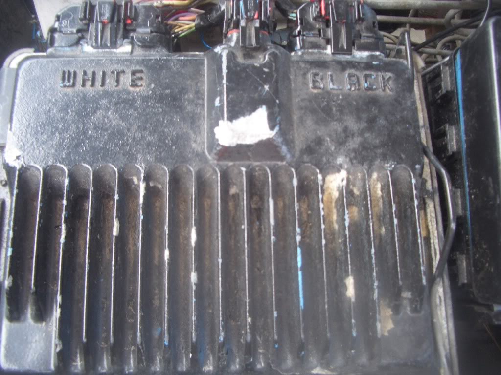
Unplug this harness. Now on the back of the harness there are tabs which hold it in place. Pop these loose and open the harness.
You can now see a bunch of wires and Pin Numbers corresponding to those wires. Locate Pin 18 (Black Wire with a white stripe). Double check the Pin with the number to be sure it is Pin 18. Now you need to release the Clip on top of the harness. Simply push on the 2 side tabs and it will release. You should now have a connector that looks like this
Last edited by aapstealth; February 2nd, 2011 at 11:40 AM.
 February 2nd, 2011, 11:08 AM
#2
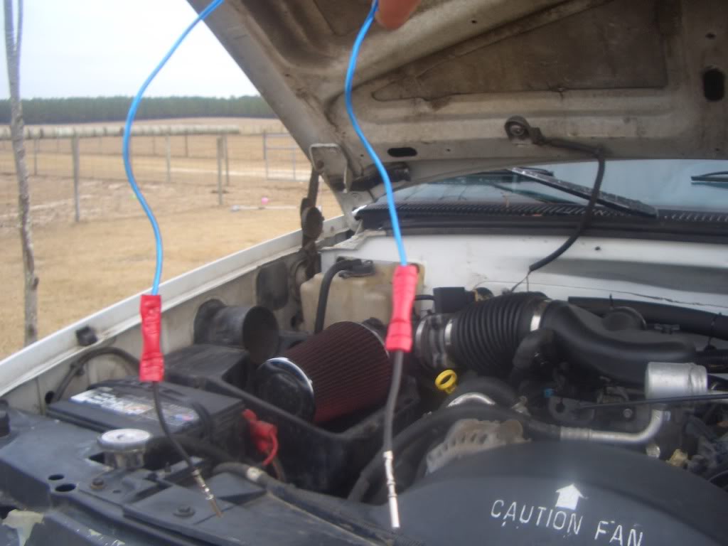
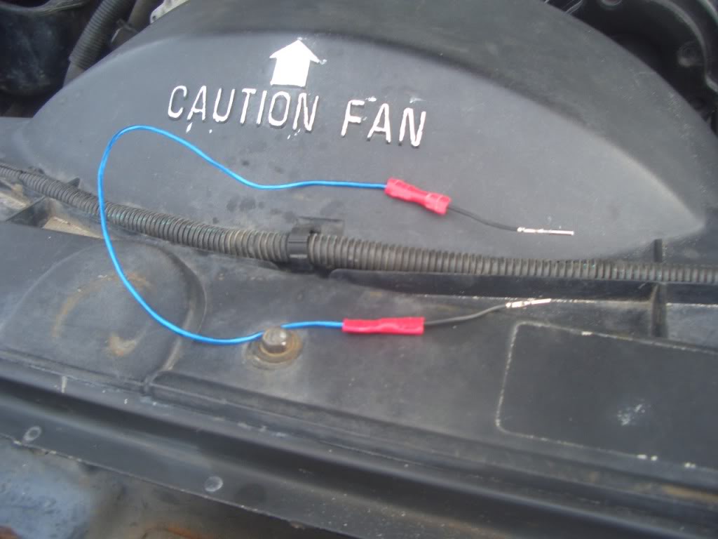
Next you can try and pull the pin 18 wire (Black with a White stripe) through the back of the Harness. By pulling back the black tab Like this. Ignore my Shiny blue wire please.
Its very tough but you can pull the Pin thorough both Green Rubber gasket and the Black plastic plug. Or Take the less professional option and Cut the wire back in the harness pull the Pin Forward and upward then reattach it in the next step. This is much easier but can cause issues if you ever need to sell the truck reuse the harness etc.
Now that you have done this reattach the pin connector at the top Part that snaps into the white clips on top of this. Ignore blue wire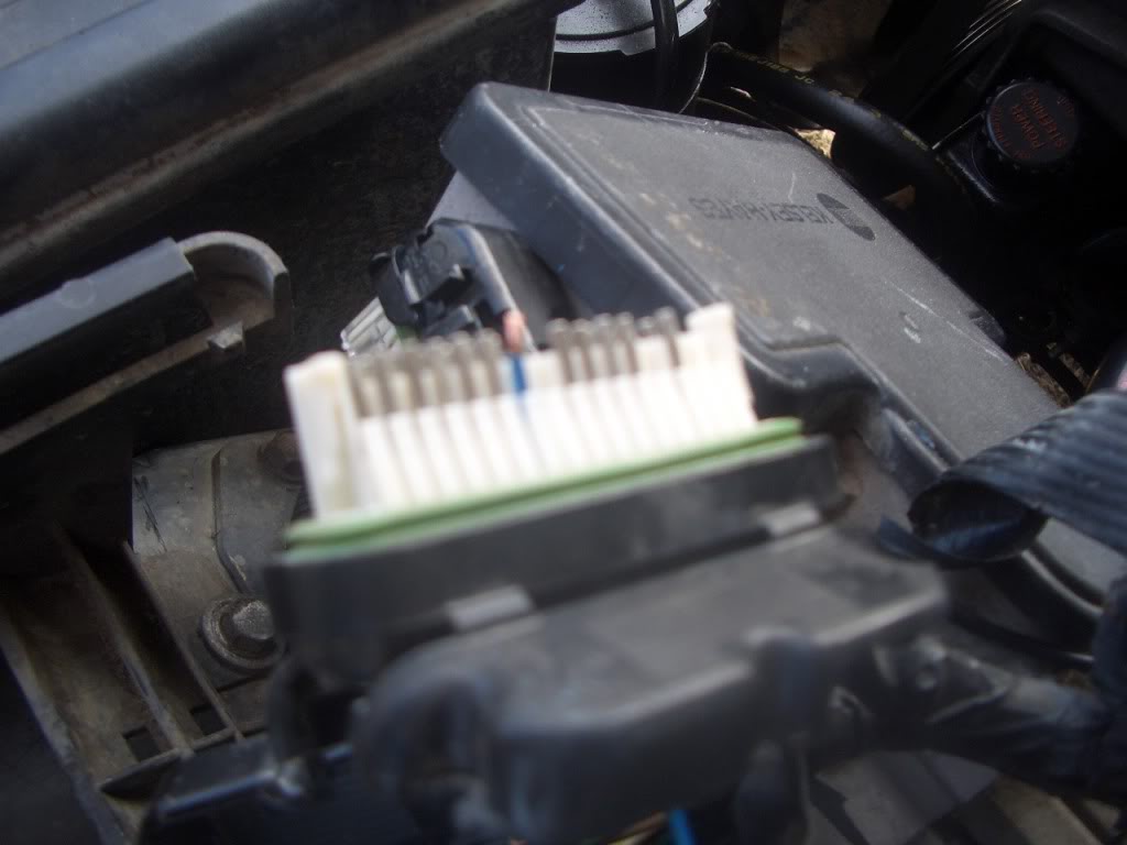
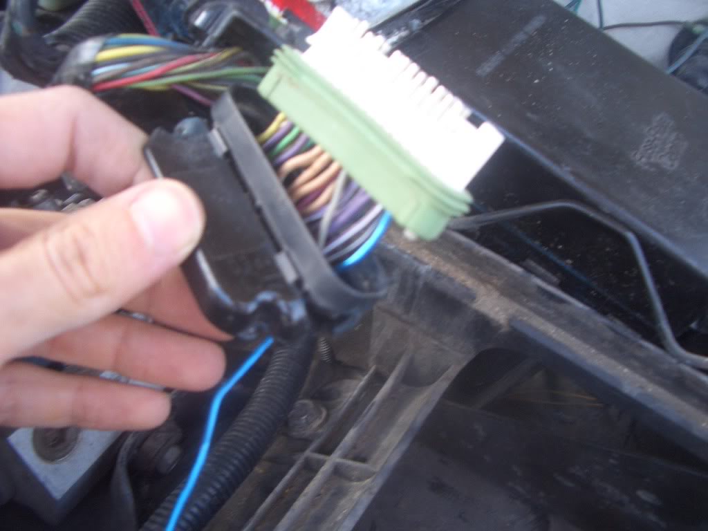
Next Locate the Blue Plug in you will have to flip the ECM over. It says Blue and will Have a Blue Pin cover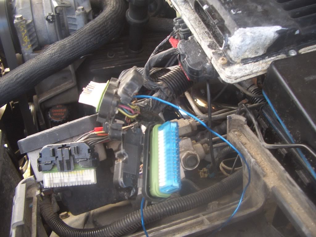
Again unplug and undo the black clips which hold the harness in place
so it looks like this
Now this time locate Pin 23 it will be open nothing used. Unplug the Blue clip that holds the pins in place up top
Now simply Push in the Wire and connector that you took out of PIN 18 on the WHITE,Grey plug in. Through both the black plastic and Green Rubber. If your having issues take a small finish nail and GENTLY plush it through the back 1st. Now push your pin in place until it sits flush like the rest. Again ignore my Shiny blue wire. Now snap your blue cover back on
 And push this plug aside.
Its very tough but you can pull the Pin thorough both Green Rubber gasket and the Black plastic plug. Or Take the less professional option and Cut the wire back in the harness pull the Pin Forward and upward then reattach it in the next step. This is much easier but can cause issues if you ever need to sell the truck reuse the harness etc.
Now that you have done this reattach the pin connector at the top Part that snaps into the white clips on top of this. Ignore blue wire
Next Locate the Blue Plug in you will have to flip the ECM over. It says Blue and will Have a Blue Pin cover
Again unplug and undo the black clips which hold the harness in place
so it looks like this
Now this time locate Pin 23 it will be open nothing used. Unplug the Blue clip that holds the pins in place up top
Now simply Push in the Wire and connector that you took out of PIN 18 on the WHITE,Grey plug in. Through both the black plastic and Green Rubber. If your having issues take a small finish nail and GENTLY plush it through the back 1st. Now push your pin in place until it sits flush like the rest. Again ignore my Shiny blue wire.
Now snap your blue cover back on And push this plug aside.
Last edited by aapstealth; February 2nd, 2011 at 11:51 AM.
February 2nd, 2011, 11:40 AM
#3
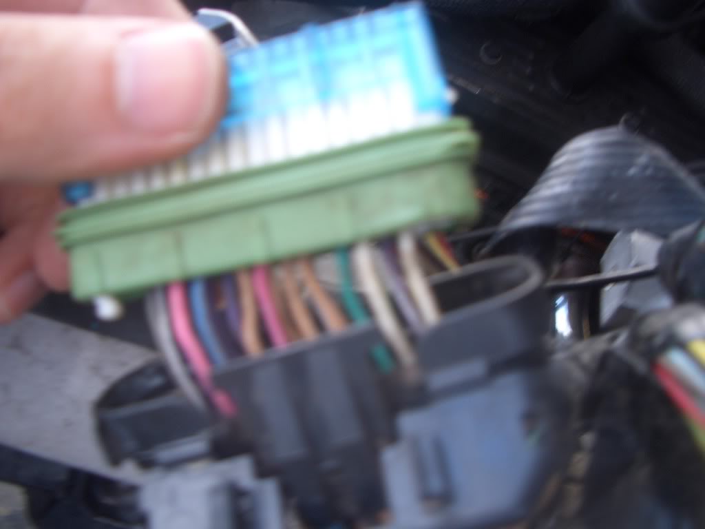
Next Locate the Red Plug in. It will say red and have a red cover
Again through these pics ignore my SHINY Blue wire it was a failed attempt at something else.
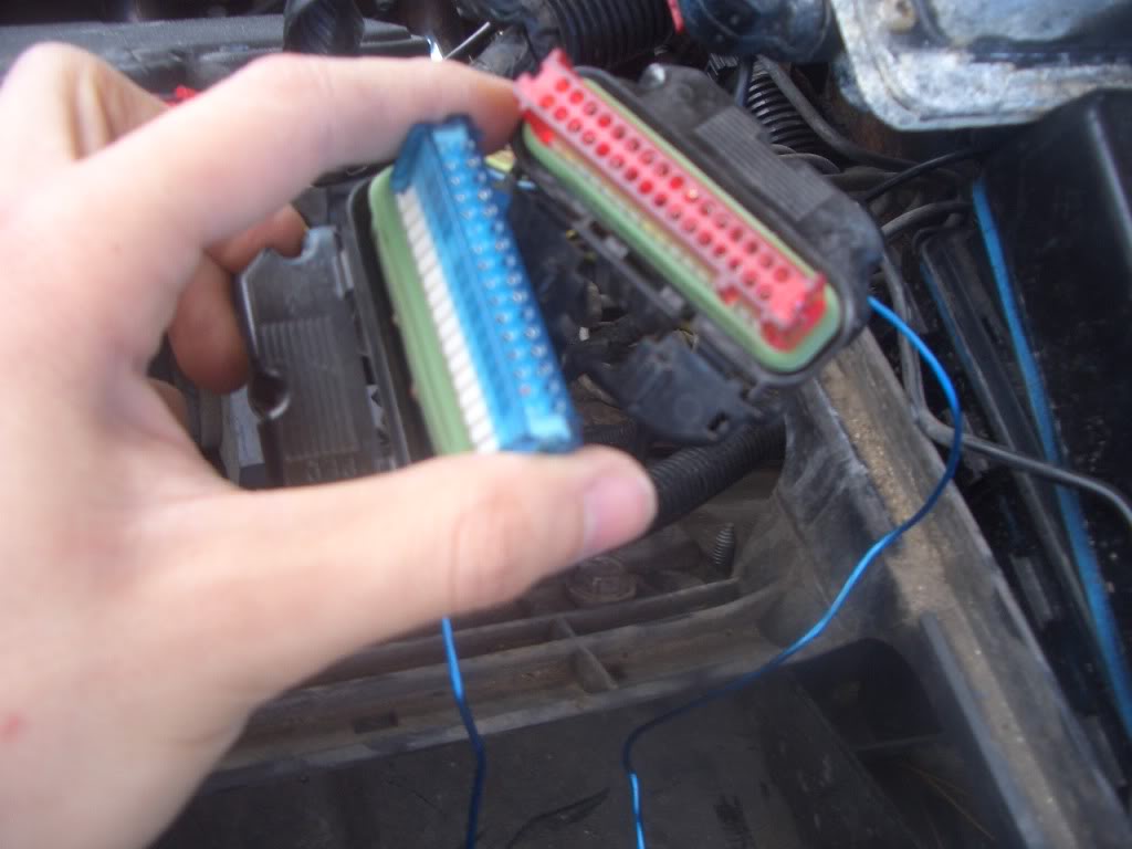
Now on the back of this RED plug in you will have to again unsnap the back taps to see this and Locate PIN 26

It will be open with nothing in it. If you bought the kit #12167310 You paid $50 for a jumper wire that will simply plug into this open pin and PIN 18 the Pin you made open on the WHITE, GREY or Clear plug in. Remember the spot you took the Black wire with a white stripe out of. It is now open as well. Now instead of paying $50 you could do like I did. Run to you local U-pull it and cut a few Ends off a wiring harness off any GM vehicle with the same pins and make your own jumper wire. Like this
I recommend using solder on any cuts and connections you make I used a Butt connector only to verify it worked.
Now Pug one end into PIN 26 on the back of the Red Plug and ensure it goes in Flush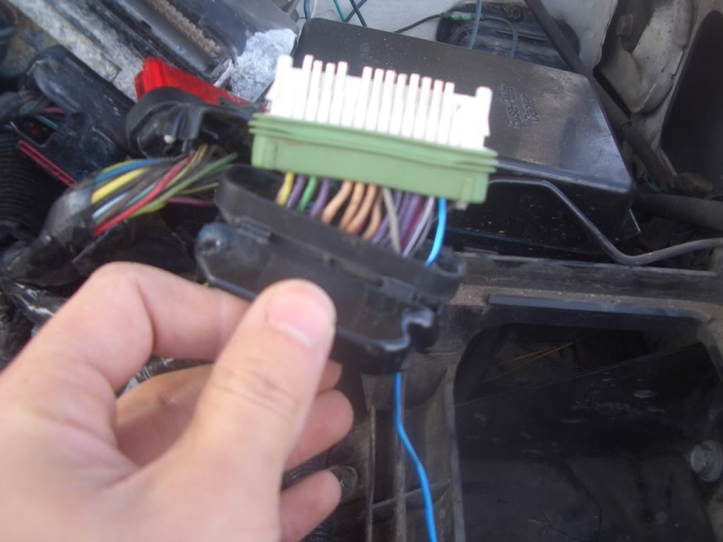
Snap the Red connector Back in at the top. Do the Same thing on Pin 18 from the WHITE GREY or Clear connector. You will now have a Wire that Connects PIN 26 from the Red Plug in to PIN 18 on the WHITE, GREY or CLEAR plug in.
Its best to push the connector in through both the back of the Black plastic and Green gasket. Just like the factory wiring
Again use a small finish nail clear the way if your having problems. Now zip tie all wire together PUT Di-electric grease on all the plug in removed and plug in everything.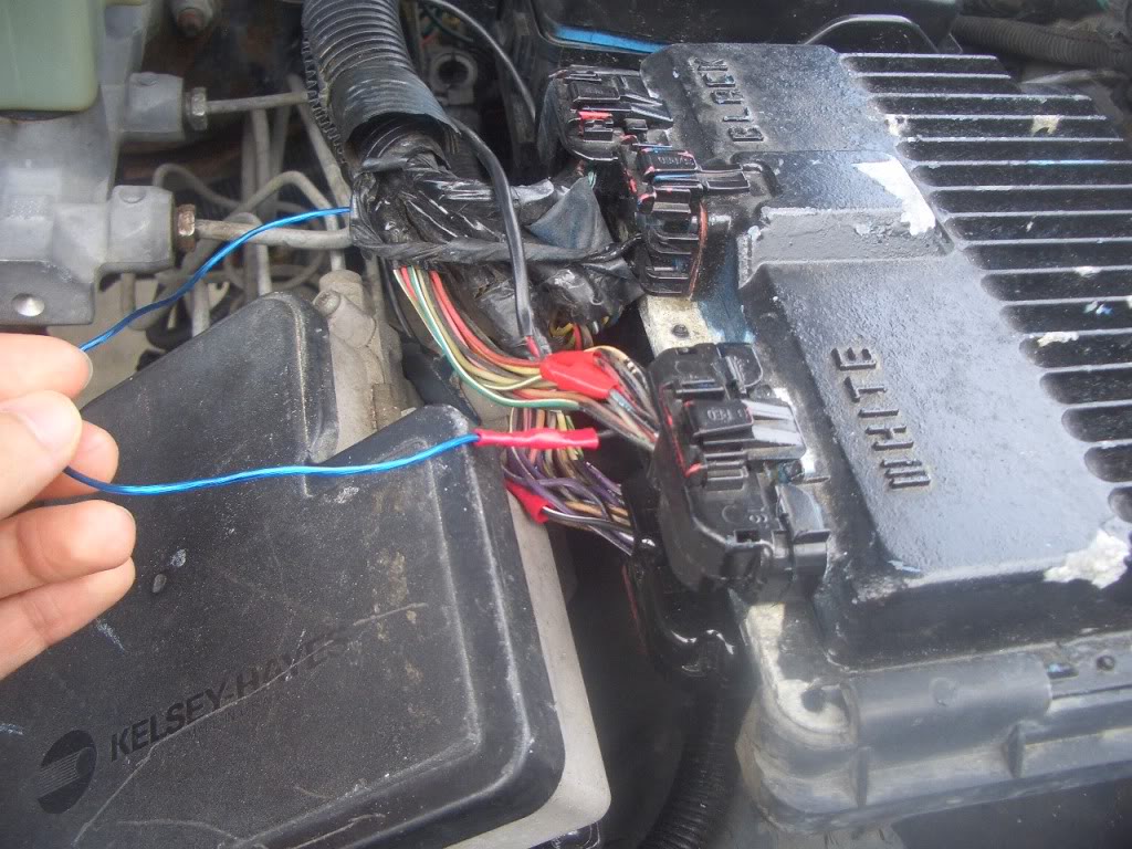
Be sure RED goes to red labeled on top of the ECM Blue to blue etc. Reconnect your battery and start truck. If you get any sort of hiccup strange Idle anything out of the ordinary turn the truck off and double check all connections. Here is a quick guide from GM about the procedure
Correction
Using harness jumper wire and instruction kit, P/N 12167310, revise the wiring harness at the VCM connector. Corrections were made to the VCM beginning 2/14/96. The corrected VCMs are identified with service number 16244210 on the VCM identification label.
Procedure
The following is a summary of the instructions included with the service kit:
1. Remove the negative terminal from the battery.
2. Move the wire located at connector J3 (WHITE/GREY/CLEAR), pin 18 to connector J1 (BLUE), pin 23.
3. Install the jumper wire between connector J2 (RED), pin 26 and connector J3 (WHITE/GREY/CLEAR), pin 18.
4. Install the tag included in the kit around the VCM wiring harness. This tag notes that the wiring harness has been modified.
5. Reconnect the negative battery terminal.
Road test to verify that the condition has been corrected. If any of the following conditions are noted, the transmission should be repaired or replaced using the most cost effective method. Canadian dealers should repair the transmission.
1. Transmission fluid oxidation or excessive sediment.
2. Transmission slip or flare after this service fix is performed.
3. DTC P1870 is stored on a 4L60-E (M30).
The following tools are available from Kent-Moore (1-800-345-2233) for use in removing and relocating the VCM wires:
1. J 41758 Terminal Tool; used to remove the wire from the VCM connector.
2. J 41759 Punch; used to punch a new hole through the connector seal
Again through these pics ignore my SHINY Blue wire it was a failed attempt at something else.
Now on the back of this RED plug in you will have to again unsnap the back taps to see this and Locate PIN 26
It will be open with nothing in it. If you bought the kit #12167310 You paid $50 for a jumper wire that will simply plug into this open pin and PIN 18 the Pin you made open on the WHITE, GREY or Clear plug in. Remember the spot you took the Black wire with a white stripe out of. It is now open as well. Now instead of paying $50 you could do like I did. Run to you local U-pull it and cut a few Ends off a wiring harness off any GM vehicle with the same pins and make your own jumper wire. Like this
I recommend using solder on any cuts and connections you make I used a Butt connector only to verify it worked.
Now Pug one end into PIN 26 on the back of the Red Plug and ensure it goes in Flush
Snap the Red connector Back in at the top. Do the Same thing on Pin 18 from the WHITE GREY or Clear connector. You will now have a Wire that Connects PIN 26 from the Red Plug in to PIN 18 on the WHITE, GREY or CLEAR plug in.
Its best to push the connector in through both the back of the Black plastic and Green gasket. Just like the factory wiring
Again use a small finish nail clear the way if your having problems. Now zip tie all wire together PUT Di-electric grease on all the plug in removed and plug in everything.
Be sure RED goes to red labeled on top of the ECM Blue to blue etc. Reconnect your battery and start truck. If you get any sort of hiccup strange Idle anything out of the ordinary turn the truck off and double check all connections. Here is a quick guide from GM about the procedure
Correction
Using harness jumper wire and instruction kit, P/N 12167310, revise the wiring harness at the VCM connector. Corrections were made to the VCM beginning 2/14/96. The corrected VCMs are identified with service number 16244210 on the VCM identification label.
Procedure
The following is a summary of the instructions included with the service kit:
1. Remove the negative terminal from the battery.
2. Move the wire located at connector J3 (WHITE/GREY/CLEAR), pin 18 to connector J1 (BLUE), pin 23.
3. Install the jumper wire between connector J2 (RED), pin 26 and connector J3 (WHITE/GREY/CLEAR), pin 18.
4. Install the tag included in the kit around the VCM wiring harness. This tag notes that the wiring harness has been modified.
5. Reconnect the negative battery terminal.
Road test to verify that the condition has been corrected. If any of the following conditions are noted, the transmission should be repaired or replaced using the most cost effective method. Canadian dealers should repair the transmission.
1. Transmission fluid oxidation or excessive sediment.
2. Transmission slip or flare after this service fix is performed.
3. DTC P1870 is stored on a 4L60-E (M30).
The following tools are available from Kent-Moore (1-800-345-2233) for use in removing and relocating the VCM wires:
1. J 41758 Terminal Tool; used to remove the wire from the VCM connector.
2. J 41759 Punch; used to punch a new hole through the connector seal
May 1st, 2012, 7:01 PM
#4
CF Beginner

Join Date: Mar 2012
Posts: 8
Likes: 0
Received 0 Likes
on
0 Posts
aapstealth:
I have some technique questions on removing the wires. I have figured out the other steps and have the jumper wire from GM.
Dealer wants 2 to 2 1/2 hours to do this procedure. I don't mind paying a fair price but since it's my truck I don't think that is a 2 and 1/2 hour job and feel like I'm being overcharged. I usually like to get my hands greasy and learn about my truck and what is making it tick. Nothing at all personal to any honest GM tech. For one thing this TSB is just one thing in a long list of culprits I'm working on.
Thanks for getting back to me.
Dave
 May 2nd, 2012, 8:50 AM
#6
CF Beginner
Join Date: Mar 2012
Posts: 8
Likes: 0
Received 0 Likes
on
0 Posts
Shamrock:
I am troubleshooting some trouble codes for a 1996 Silverado K2500 with the 4L80E tranny. I had a "limp mode" situation that I began to investigate.
A Snap On Diagnostic Scanner gave me the following codes. TPS intermittent low voltage, Solenoild B stuck off or performance, trans component slipping, and undefined gear ratios.
Since then I have replaced the TPS with a new AC Delco sensor, dropped the pan and replaced the Sol A and B. and inspected the pan for metal debris, etc.
Currently the truck is running much better and hasn't gone back into the limp mode, stuck in 2nd gear, high reving , yada, yada. Before this I would pull off the road and reset my ignition key.
My truck's PCM was before the year end fix in 1996 with the corrected PCM from GM as indicated by the numbered sticker. My TSB "jumper wire kit" has the sticker to tag the PCM.
I think that in chasing down any "electrical gremlins" that I will be able to mark one more item off the list.
Any help or advice you can provide is appreciated. I went back and read the procedure sheet with my $55 GM jumper wire kit and am currently looking to get the correct "terminal release tool."
I can see how the pin has to be raised to clear the locking ramp in the connector.
Dave
July 2nd, 2015, 9:01 PM
#7
New User
Awaiting E-mail Confirmation
Awaiting E-mail Confirmation

Join Date: Jul 2015
Posts: 1
Likes: 0
Received 0 Likes
on
0 Posts
there is a wire in both 23 and 26 what do I do with these
Next you can try and pull the pin 18 wire (Black with a White stripe) through the back of the Harness. By pulling back the black tab Like this. Ignore my Shiny blue wire please.

Its very tough but you can pull the Pin thorough both Green Rubber gasket and the Black plastic plug. Or Take the less professional option and Cut the wire back in the harness pull the Pin Forward and upward then reattach it in the next step. This is much easier but can cause issues if you ever need to sell the truck reuse the harness etc.
Now that you have done this reattach the pin connector at the top Part that snaps into the white clips on top of this. Ignore blue wire
Next Locate the Blue Plug in you will have to flip the ECM over. It says Blue and will Have a Blue Pin cover
Again unplug and undo the black clips which hold the harness in place
so it looks like this
Now this time locate Pin 23 it will be open nothing used. Unplug the Blue clip that holds the pins in place up top
Now simply Push in the Wire and connector that you took out of PIN 18 on the WHITE,Grey plug in. Through both the black plastic and Green Rubber. If your having issues take a small finish nail and GENTLY plush it through the back 1st. Now push your pin in place until it sits flush like the rest. Again ignore my Shiny blue wire. Now snap your blue cover back on
 And push this plug aside.
Its very tough but you can pull the Pin thorough both Green Rubber gasket and the Black plastic plug. Or Take the less professional option and Cut the wire back in the harness pull the Pin Forward and upward then reattach it in the next step. This is much easier but can cause issues if you ever need to sell the truck reuse the harness etc.
Now that you have done this reattach the pin connector at the top Part that snaps into the white clips on top of this. Ignore blue wire
Next Locate the Blue Plug in you will have to flip the ECM over. It says Blue and will Have a Blue Pin cover
Again unplug and undo the black clips which hold the harness in place
so it looks like this
Now this time locate Pin 23 it will be open nothing used. Unplug the Blue clip that holds the pins in place up top
Now simply Push in the Wire and connector that you took out of PIN 18 on the WHITE,Grey plug in. Through both the black plastic and Green Rubber. If your having issues take a small finish nail and GENTLY plush it through the back 1st. Now push your pin in place until it sits flush like the rest. Again ignore my Shiny blue wire.
Now snap your blue cover back on And push this plug aside.Trending Topics
October 13th, 2018, 2:29 PM
#8
CF Beginner

Join Date: Oct 2018
Posts: 1
Likes: 0
Received 0 Likes
on
0 Posts
Can you give some symptoms that this procedure will help with? I'm chasing a TPS problem. I tested the words, they are good. I required the TPS things went wrong, I undid the change and back to the original problem.
 September 3rd, 2021, 5:33 PM
#10
CF Beginner

Join Date: Sep 2021
Posts: 2
Likes: 0
Received 0 Likes
on
0 Posts
Next Locate the Red Plug in. It will say red and have a red cover
Attachment 13142
Again through these pics ignore my SHINY Blue wire it was a failed attempt at something else.
Now on the back of this RED plug in you will have to again unsnap the back taps to see this and Locate PIN 26
Attachment 13143
It will be open with nothing in it. If you bought the kit #12167310 You paid $50 for a jumper wire that will simply plug into this open pin and PIN 18 the Pin you made open on the WHITE, GREY or Clear plug in. Remember the spot you took the Black wire with a white stripe out of. It is now open as well. Now instead of paying $50 you could do like I did. Run to you local U-pull it and cut a few Ends off a wiring harness off any GM vehicle with the same pins and make your own jumper wire. Like this
Attachment 13144
Attachment 13145
I recommend using solder on any cuts and connections you make I used a Butt connector only to verify it worked.
Now Pug one end into PIN 26 on the back of the Red Plug and ensure it goes in Flush Attachment 13146
Snap the Red connector Back in at the top. Do the Same thing on Pin 18 from the WHITE GREY or Clear connector. You will now have a Wire that Connects PIN 26 from the Red Plug in to PIN 18 on the WHITE, GREY or CLEAR plug in.
Its best to push the connector in through both the back of the Black plastic and Green gasket. Just like the factory wiring
Attachment 13143
Again use a small finish nail clear the way if your having problems. Now zip tie all wire together PUT Di-electric grease on all the plug in removed and plug in everything. Attachment 13148
Be sure RED goes to red labeled on top of the ECM Blue to blue etc. Reconnect your battery and start truck. If you get any sort of hiccup strange Idle anything out of the ordinary turn the truck off and double check all connections. Here is a quick guide from GM about the procedure
Correction
Using harness jumper wire and instruction kit, P/N 12167310, revise the wiring harness at the VCM connector. Corrections were made to the VCM beginning 2/14/96. The corrected VCMs are identified with service number 16244210 on the VCM identification label.
Procedure
The following is a summary of the instructions included with the service kit:
1. Remove the negative terminal from the battery.
2. Move the wire located at connector J3 (WHITE/GREY/CLEAR), pin 18 to connector J1 (BLUE), pin 23.
3. Install the jumper wire between connector J2 (RED), pin 26 and connector J3 (WHITE/GREY/CLEAR), pin 18.
4. Install the tag included in the kit around the VCM wiring harness. This tag notes that the wiring harness has been modified.
5. Reconnect the negative battery terminal.
Road test to verify that the condition has been corrected. If any of the following conditions are noted, the transmission should be repaired or replaced using the most cost effective method. Canadian dealers should repair the transmission.
1. Transmission fluid oxidation or excessive sediment.
2. Transmission slip or flare after this service fix is performed.
3. DTC P1870 is stored on a 4L60-E (M30).
The following tools are available from Kent-Moore (1-800-345-2233) for use in removing and relocating the VCM wires:
1. J 41758 Terminal Tool; used to remove the wire from the VCM connector.
2. J 41759 Punch; used to punch a new hole through the connector seal
The plug in the middle with no color and has 5 pins the wires on my plug are cut . Where do the wires go to