When you click on links to various merchants on this site and make a purchase, this can result in this site earning a commission. Affiliate programs and affiliations include, but are not limited to, the eBay Partner Network.
You're gonna have to probe deeper. Use continuity mode on your DMM. Probe the data bus pins between module and module to make sure they have a good connection. Check power supply and ground connections too.
I measured the resistance between the CAN-H and CAN-L pins on the OBD2 port below the driver knee. I measured 60 ohms. If the data bus was open anywhere, I thought that I would get a different resistance but this is all new to me. All of the dash lights seem to function properly even during the no crank situation. The PRNDM1 seems to always work unless I disconnect the X3 connector. The battery is good and not a source of problem.
The issue seems to be intermittent. I can recreate a no start / service airbag display if I let the vehicle sit for a long period of time (so far I have only tried 24 hours); put the key in; turn the ignition to run; wait 1 sec; turn key to crank. The starter will engage for .5 seconds and the stop. All lights on dash go out. When I release the key back to run, the dash lights reappear and chimes 5 times and then I get 33 fast chimes with the service airbad message.
The engine will not start until I do the following. It I take the key out, open the drivers door, wait 10 seconds, put key in and turn to run; wait 4 seconds; then turn to start. The engine will then start and no messages are displayed. The engine will continue to start (most of the time) with any attempt after this and seems to function normally.
I need to figure out what sequences/sensor conditions in the computers will cause the "service airbag" message to appear with 33 chimes.
Last edited by rockfishon; January 26th, 2019 at 12:54 PM.
I measured the resistance between the CAN-H and CAN-L pins on the OBD2 port below the driver knee. I measured 60 ohms. If the data bus was open anywhere, I thought that I would get a different resistance but this is all new to me.
All you did was measure the termination resistors. Nodes on the CAN bus are in parallel, not series. If one module becomes disconnected, bus integrity is not affected.
Originally Posted by rockfishon
The battery is good and not a source of problem.
Originally Posted by mountainmanjoe
Check power supply and ground connections too.
Originally Posted by Artie1
verify power, ground to the modules
I did not mean check the battery. I meant measure the power pins on each module to make sure it's getting 12V. Also measure continuity between the chassis and the ground pins at each module.
Originally Posted by rockfishon
The issue seems to be intermittent... The engine will not start until I do the following. It I take the key out, open the drivers door, wait 10 seconds, ... after this and seems to function normally.
Symptoms of a U0100 DTC code may include.
� Vehicle stalls and will not crank or restart
� Vehicle may start after sitting idle for a period of time, however, it would be risky to operate because it could fail again at a most inopportune moment
I can recreate a no start / service airbag display if I let the vehicle sit for a long period of time (so far I have only tried 24 hours); put the key in; turn the ignition to run; wait 1 sec; turn key to crank. The starter will engage for .5 seconds and the stop. All lights on dash go out. When I release the key back to run, the dash lights reappear and chimes 5 times and then I get 33 fast chimes with the service airbad message.
The engine will not start until I do the following. It I take the key out, open the drivers door, wait 10 seconds, put key in and turn to run; wait 4 seconds; then turn to start. The engine will then start and no messages are displayed. The engine will continue to start (most of the time) with any attempt after this and seems to function normally.
I need to figure out what sequences/sensor conditions in the computers will cause the "service airbag" message to appear with 33 chimes.
This is a very detailed explanation, and certainly a weird issue. If you have airbag codes and loss of communication codes among all modules, I would imagine the voltage being all over the range might be the culprit.
Have you verified the battery is good and charged? I would recommend using a load tester for this. And I would also load test all house/secondary batteries.
If battery is good, are terminals tightly secured?
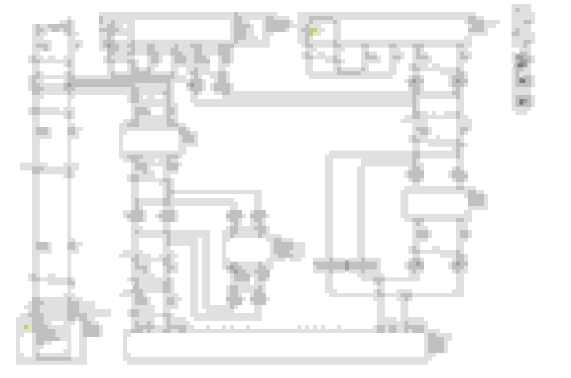
Can some one help me understand the CAN bus layout for my vehicle? The diagram show 3 x 120 ohm resisters instead of 2. Also, why do most of the modules have 2 connections to the CAN bus? I would think that it would only be one if the module was a node on the bus.
BODY BUILDER MANUAL FOR 2015 CHEVROLET EXPRESS/GMC SAVANA ELECTRICAL SECTION - page 120
I have an digital oscilloscope with CAN bus decode on order and will be posting captures hopefully soon.
Last edited by rockfishon; February 1st, 2019 at 8:33 AM.
This is a very detailed explanation, and certainly a weird issue. If you have airbag codes and loss of communication codes among all modules, I would imagine the voltage being all over the range might be the culprit.
Have you verified the battery is good and charged? I would recommend using a load tester for this. And I would also load test all house/secondary batteries.
If battery is good, are terminals tightly secured?
Thanks for the reply. I have tested the battery and it is good. All terminals are clean with good connections.
I'd look at that charging relay. They can stick closed sometimes. And if the house battery is down, it'll draw down the main.
I agree, my bet is this will be a power distribution issue, the computers protect themselves when they see low voltage/poor ground. If you want to look at anything go to the bcm battery voltage input pins and then turn the ignition key on and see what you are reading (while you are having this issue).
Also, why do most of the modules have 2 connections to the CAN bus?
You see those 3 letter codes in box? Those are RPO codes. For example, when you see [UE1] it means vans with that option have this circuit. If there's a '-' in there (eg [-UE1] ) , then that's the circuit for vans without that option.
However, your van does have two buses. A high speed CAN, used for critical things like engine tuning and safety restraints. And a low speed CAN for non-critical things, like radio buttons on the steering wheel etc. Some modules are connected to both buses (eg BCM), however I think the two connections would be shown on different diagrams. I'm pretty sure the codes you are getting only refer to the high speed CAN.
I have an digital oscilloscope with CAN bus decode on order and will be posting captures hopefully soon.
I really think you are barking down the wrong rabbit hole. Analyzing the signals will be very time consuming, and ultimately unproductive towards solving your no-start.
If you checked to make sure the modules have good solid connections to each other, power, and ground, then the next step is to start swapping modules.
I think I understand, 2 different transmission configurations with terminating resistors shown in the diagram. Thanks. Scope is due to arrive next Thursday. I will be able to plot voltages to the BCM while cranking as well as do a detailed signal inspection of the CAN bus. More to come.

 January 26th, 2019, 3:17 AM