99 S-10 codes
#1
New to the site, what i've read i like. I have a 99 s-10 2.2 and it has three codes coming up. I looked them up but do not know what they mean. need some help. PO113 Intake Air Temperature Circuit High Input 420 Catalyst System Efficiency Below Threshold (Bank1) 440 Evaporative Emission ontrol System Malfunction any help would be appreciated.
#2
CF Monarch
I have the DTC explaination for PO420, but I'm still looking for the others.
P0420 - Catalyst System Efficiency Below Threshold (Bank 1)
Schematic
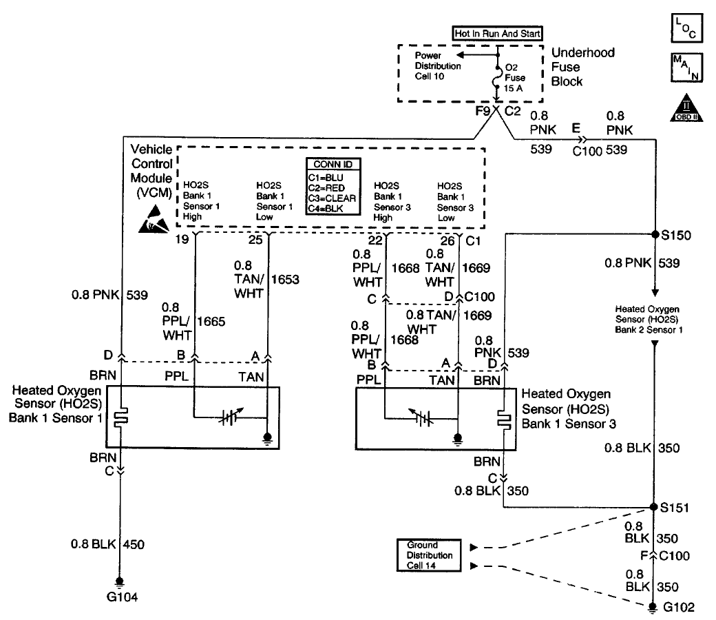
CIRCUIT DESCRIPTION
This diagnostic test designed in order to measure the efficiency of the Three-way Catalytic Converter (TWC) system. Catalytic convertor efficiency is a measure of its ability to store oxygen after converting the levels of Hydrocarbon (HC) , Carbon Monoxide (CO) , and Oxides Of Nitrogen (NOx) to less harmful gases. The control module is able to evaluate the catalyst efficiency once the vehicle has met the enable criteria and the vehicle is at idle instead of the steady cruise speeds used in the past. Once the conditions for running this Diagnostic Trouble Code (DTC) are met, the control module commands either a lean or rich air/fuel ratio depending on the current state of the exhaust oxygen level. The control module issues a rich command if the exhaust is currently lean, or a lean command if the exhaust is currently rich. After completion of the first command, a second and opposite command is issued.
For example, if the control module were to command a rich mixture, the upstream Heated Oxygen Sensor (HO2S) voltage would increase immediately. The rich mixture is delayed in reaching the downstream HO2S due to the conversion process occurring within the converter. The higher the efficiency, the more the delay before the rich or lean mixture is detected by the downstream Oxygen (O2) sensor. As a result of the lower conversion efficiency within a damaged or poisoned catalyst, the delay in the rich or lean mixture reaching the downstream O2 sensor is significantly shorter. This DTC monitors the amount of time required for both the upstream and downstream HO2S voltages to cross a calibrated voltage threshold in response to the rich or lean command.
CONDITIONS FOR RUNNING THE DTC
* No active secondary AIR DTCs
* No active CMP sensor DTCs
* No active ECT sensor DTCs
* No active EGR DTCs
* No active Fuel Trim DTCs
* No active IAC DTCs
* No active IAT sensor DTCs
* No active MAF sensor DTCs
* No active MAP sensor DTCs
* No active O2 sensor DTCs
* No active transmission DTCs
* No active EVAP system DTCs
* No active TP sensor DTCs
* No active VS sensor DTCs
* No active misfire DTCs
* The engine speed is 900 RPM or more for more than 35 seconds since the last idle period.
* The engine has been running for more than 346 seconds and the long term fuel trim is stable.
* The predicted catalyst temperature is more than 475°C (887°F) .
* The system is in Closed Loop.
* The BARO is 73 kPa or more.
* The IAT is between -7 to 117°C (20-167°F) .
* The ECT is between 75-117°C (167-243°F) .
* The engine has been idling for less than 60 seconds .
* The actual engine speed is within 100 RPM of the desired idle speed.
CONDITIONS FOR SETTING THE DTC
The VCM determined that the oxygen storage capacity of the catalyst has degraded below a calibrated threshold.
ACTION TAKEN WHEN THE DTC SETS
* The control module illuminates the Malfunction Indicator Lamp (MIL) if a failure is detected during 2 consecutive key cycles.
* The control module sets the DTC and records the operating conditions at the time the diagnostic failed. The failure information is stored in the scan tool Freeze Frame and Failure Records.
CONDITIONS FOR CLEARING THE MIL OR DTC
* The control module turns OFF the MIL after 3 consecutive drive trips when the test has run and passed.
* A history DTC will clear if no fault conditions have been detected for 40 warm-up cycles. A warm-up cycle occurs when the coolant temperature has risen 22°C (40°F) from the startup coolant temperature and the engine coolant reaches a temperature that is more than 70°C (158°F) during the same ignition cycle.
* Use a scan tool in order to clear the DTCs.
DIAGNOSTIC AIDS
The use of fuel with a high sulfur or lead content can degrade a marginal convertor's performance. Be sure to check the fuel quality.
An intermittent may be caused by any of the following conditions:
* A poor connection
* Rubbed through wire insulation
* A broken wire inside the insulation
Thoroughly inspect any circuitry that is suspected of causing the intermittent complaint. Refer to Testing for Intermittent and Poor Connections in Diagrams.
If a repair is necessary, refer to Wiring Repairs or Connector Repairs in Diagrams.
Diagnostic Chart
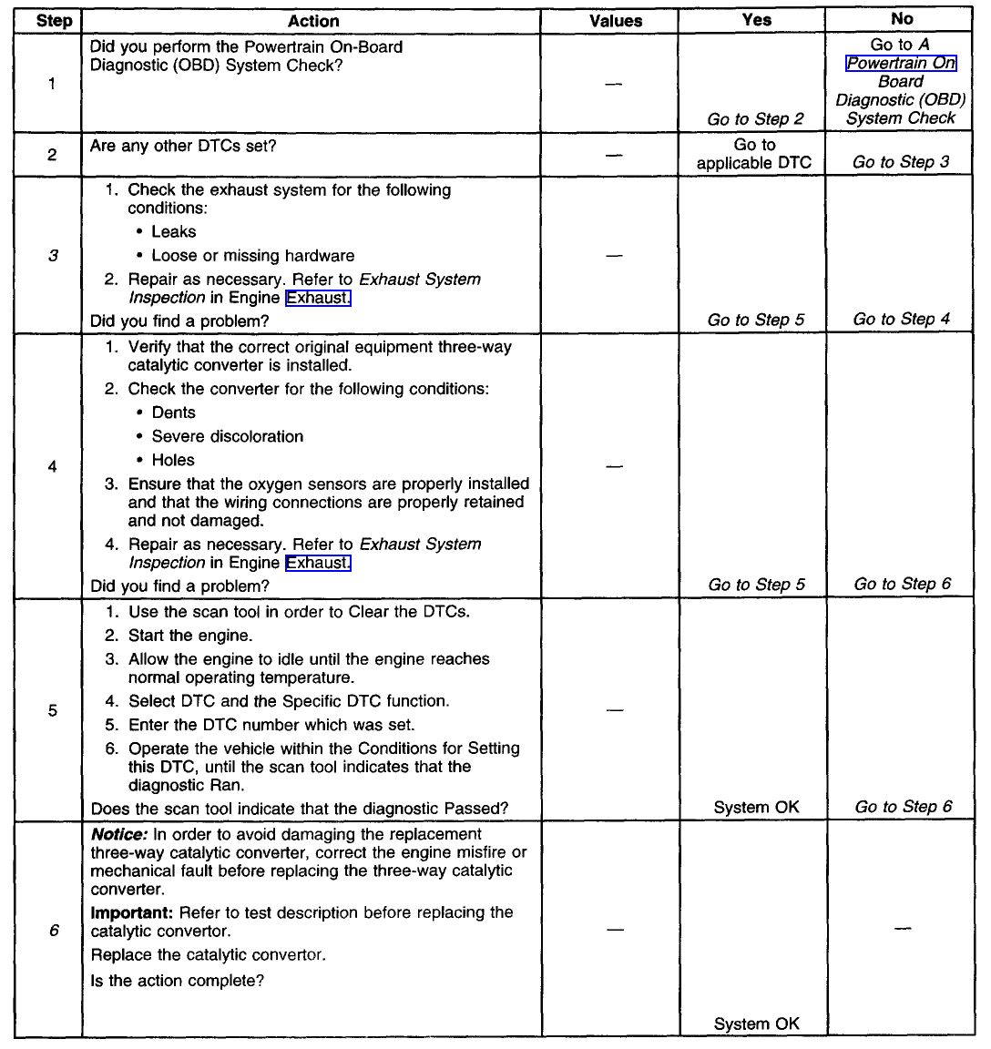
TEST DESCRIPTION
The numbers below refer to the step numbers in the diagnostic table.
3. This table checks for conditions that can cause the three-way catalytic converter efficiency to appear degraded. Inspect and repair the exhaust system as necessary.
6. Before the three-way catalytic converter is replaced, make sure that the following conditions are not present:
o Misfire
o High engine oil consumption or coolant consumption
o Retarded spark timing or weak spark.
P0420 - Catalyst System Efficiency Below Threshold (Bank 1)
Schematic

CIRCUIT DESCRIPTION
This diagnostic test designed in order to measure the efficiency of the Three-way Catalytic Converter (TWC) system. Catalytic convertor efficiency is a measure of its ability to store oxygen after converting the levels of Hydrocarbon (HC) , Carbon Monoxide (CO) , and Oxides Of Nitrogen (NOx) to less harmful gases. The control module is able to evaluate the catalyst efficiency once the vehicle has met the enable criteria and the vehicle is at idle instead of the steady cruise speeds used in the past. Once the conditions for running this Diagnostic Trouble Code (DTC) are met, the control module commands either a lean or rich air/fuel ratio depending on the current state of the exhaust oxygen level. The control module issues a rich command if the exhaust is currently lean, or a lean command if the exhaust is currently rich. After completion of the first command, a second and opposite command is issued.
For example, if the control module were to command a rich mixture, the upstream Heated Oxygen Sensor (HO2S) voltage would increase immediately. The rich mixture is delayed in reaching the downstream HO2S due to the conversion process occurring within the converter. The higher the efficiency, the more the delay before the rich or lean mixture is detected by the downstream Oxygen (O2) sensor. As a result of the lower conversion efficiency within a damaged or poisoned catalyst, the delay in the rich or lean mixture reaching the downstream O2 sensor is significantly shorter. This DTC monitors the amount of time required for both the upstream and downstream HO2S voltages to cross a calibrated voltage threshold in response to the rich or lean command.
CONDITIONS FOR RUNNING THE DTC
* No active secondary AIR DTCs
* No active CMP sensor DTCs
* No active ECT sensor DTCs
* No active EGR DTCs
* No active Fuel Trim DTCs
* No active IAC DTCs
* No active IAT sensor DTCs
* No active MAF sensor DTCs
* No active MAP sensor DTCs
* No active O2 sensor DTCs
* No active transmission DTCs
* No active EVAP system DTCs
* No active TP sensor DTCs
* No active VS sensor DTCs
* No active misfire DTCs
* The engine speed is 900 RPM or more for more than 35 seconds since the last idle period.
* The engine has been running for more than 346 seconds and the long term fuel trim is stable.
* The predicted catalyst temperature is more than 475°C (887°F) .
* The system is in Closed Loop.
* The BARO is 73 kPa or more.
* The IAT is between -7 to 117°C (20-167°F) .
* The ECT is between 75-117°C (167-243°F) .
* The engine has been idling for less than 60 seconds .
* The actual engine speed is within 100 RPM of the desired idle speed.
CONDITIONS FOR SETTING THE DTC
The VCM determined that the oxygen storage capacity of the catalyst has degraded below a calibrated threshold.
ACTION TAKEN WHEN THE DTC SETS
* The control module illuminates the Malfunction Indicator Lamp (MIL) if a failure is detected during 2 consecutive key cycles.
* The control module sets the DTC and records the operating conditions at the time the diagnostic failed. The failure information is stored in the scan tool Freeze Frame and Failure Records.
CONDITIONS FOR CLEARING THE MIL OR DTC
* The control module turns OFF the MIL after 3 consecutive drive trips when the test has run and passed.
* A history DTC will clear if no fault conditions have been detected for 40 warm-up cycles. A warm-up cycle occurs when the coolant temperature has risen 22°C (40°F) from the startup coolant temperature and the engine coolant reaches a temperature that is more than 70°C (158°F) during the same ignition cycle.
* Use a scan tool in order to clear the DTCs.
DIAGNOSTIC AIDS
The use of fuel with a high sulfur or lead content can degrade a marginal convertor's performance. Be sure to check the fuel quality.
An intermittent may be caused by any of the following conditions:
* A poor connection
* Rubbed through wire insulation
* A broken wire inside the insulation
Thoroughly inspect any circuitry that is suspected of causing the intermittent complaint. Refer to Testing for Intermittent and Poor Connections in Diagrams.
If a repair is necessary, refer to Wiring Repairs or Connector Repairs in Diagrams.
Diagnostic Chart

TEST DESCRIPTION
The numbers below refer to the step numbers in the diagnostic table.
3. This table checks for conditions that can cause the three-way catalytic converter efficiency to appear degraded. Inspect and repair the exhaust system as necessary.
6. Before the three-way catalytic converter is replaced, make sure that the following conditions are not present:
o Misfire
o High engine oil consumption or coolant consumption
o Retarded spark timing or weak spark.
#4
I tried todoctor up the table below the best i could. When you cut\paste it messes it all up. Let me know if you can't read it properly and i can email it to you
DTC P0113 Intake Air Temperature (IAT) Sensor Circuit High Voltage
Circuit Description
The Intake Air Temperature (IAT) sensor is a thermistor which controls the signal voltage to the PCM. The PCM supplies a 5V reference and a ground to the sensor. When the air is cold, the resistance will be high. Whenever the intake air is warm, the resistance will be low.
Conditions for Running the DTC[align=left]•No active ECT DTC's[/align][align=left]•No active VSS DTC's[/align][align=left]•The engine run time is more than 320seconds.[/align][align=left]•The engine coolant temperature (ECT) is more than -40°C (-40°F).[/align][align=left]•The vehicle speed is less than 15mph (24km/h).[/align]
Conditions for Setting the DTC
The IAT sensor signal voltage indicates that the intake air temperature is less than -40°C (-40°F) for 3 seconds.
Action Taken When the DTC Sets[align=left]•The control module illuminates the malfunction indicator lamp (MIL) if a failure is detected during 2consecutive key cycles.[/align][align=left]•The control module sets the DTC and records the operating conditions at the time the diagnostic failed. The failure information is stored in the scan tool Freeze Frame/Failure Records.[/align]
Conditions for Clearing the MIL or DTC[align=left]•The control module turns OFF the MIL after 3consecutive drive trips when the test has run and passed.[/align][align=left]•A history DTC will clear if no fault conditions have been detected for 40warm-up cycles. A warm-up cycle occurs when the coolant temperature has risen 22°C(40°F) from the startup coolant temperature and the engine coolant reaches a temperature that is more than 70°C(158°F) during the same ignition cycle.[/align][align=left]•Use a scan tool in order to clear the DTCs.[/align]
Diagnostic Aids[align=left]•When the vehicle is at ambient temperature, compare the IAT sensor to the ECT sensor. The IAT sensor and the ECT sensor should be relatively close to each other.[/align][align=left]•Use the Temperature vs Resistance Values Table below to evaluate the possibility of a skewed sensor. Refer to Temperature Versus Resistance .[/align]An intermittent may be caused by any of the following conditions:[align=left]•A poor connection[/align][align=left]•Rubbed through wire insulation[/align][align=left]•A broken wire inside the insulation[/align]Thoroughly check any circuitry that is suspected of causing the intermittent complaint. Refer to Intermittents and Poor Connections Diagnosis in Wiring Systems.
If a repair is necessary, refer to Wiring Repairs or Connector Repairs in Wiring Systems.
Test Description
The numbers below refer to the step numbers on the Diagnostic Table.
[ol]1. The Powertrain OBD System Check prompts you to complete some of the basic checks and to store the freeze frame and failure records data on the scan tool if applicable. This creates an electronic copy of the data captured when the malfunction occurred. The scan tool stores this data for later reference.
4. This step simulates a DTCP0112. If the PCM senses the change, the PCM and wiring are OK.
5. This step will determine if the reason that the PCM did not sense the change was due to the following conditions:[align=left]•Open ground circuit[/align][align=left]•Short to voltage in the signal circuit[/align][align=left]•Malfunctioning PCM[/align]
11. Program the replacement PCM and perform the Crankshaft Position System Variation Learn Procedure. Refer to the latest Techline information for PCM programming.[/ol]
StepAction Value(s) Yes No
1 Did you perform the Powertrain -- Go to Step 2Go to Powertrain On Board Diagnostic
On-Board Diagnostic (OBD) System Check? (OBD) System Check
2Turn ON the ignition leaving the engine OFF. -30°C (-22°F) Go to Step 4 Go to Step 3
Install a scan tool.
Is the IAT sensor value less than the
specified value?
3Review the Freeze Frame data and record -30°C (-22°F)&
#5
CF Monarch
Found the bulletin on the PO440.
[hr]
P0440
Schematic
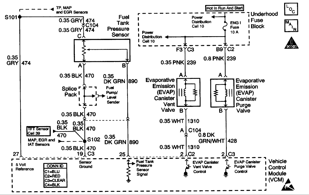
CIRCUIT DESCRIPTION
The evaporative system includes the following components:
* The fuel tank
* The EVAP vent solenoid
* The fuel tank pressure sensor
* The fuel pipes and hoses The vapor lines
* The fuel cap
* The evaporative emission canister
* The purge lines
* The EVAP purge solenoid
The evaporative leak detection diagnostic strategy is based on applying a vacuum to the EVAP system and monitoring the vacuum decay rate. The Vehicle Control Module (VCM) monitors the vacuum level via the fuel tank pressure sensor input. At an appropriate time, the EVAP purge solenoid and the EVAP vent solenoid turn ON, allowing the engine vacuum to draw a small vacuum on the entire evaporative emission system. If a sufficient vacuum level cannot be achieved, a large leak or an EVAP system malfunction is indicated. The following conditions can cause this problem:
* A disconnected or malfunctioning fuel tank pressure sensor
* A missing, malfunctioning, improperly installed, or loose fuel cap
* A disconnected, damaged, pinched, or blocked EVAP purge line
* A disconnected or damaged EVAP vent hose
* A disconnected, damaged, pinched, or blocked fuel tank vapor line
* A disconnected or malfunctioning EVAP purge solenoid
* A disconnected or malfunctioning EVAP vent solenoid
* An open ignition feed circuit to the EVAP vent or purge solenoid
* A damaged EVAP canister
* A leaking fuel sender assembly O-ring
* A leaking fuel tank or fuel filler neck
Any of the above conditions can set a DTC P0440.
CONDITIONS FOR RUNNING THE DTC
* No active MAP sensor DTCs
* No active TP sensor DTCs
* No active VS sensor DTCs
* No active O2 sensor DTCs
* No active ECT sensor DTCs
* No active IAT sensor DTCs
* DTC P0125 not active
* The system voltage is between 10-17 volts
* The fuel level is between 12.5-87 percent .
* The ECT is between 4°C-30°C (39°F-86°F)
* The IAT is between 4°C-30°C (39°F-86°F)
* The cold start temperature difference (ECT minus IAT) is less than 1.5°C when the IAT is more than the ECT or 8°C when the ECT is more than the IAT
* The BARO is more than 73 kPa
CONDITIONS FOR SETTING THE DTC
The EVAP system is unable to generate a vacuum more than a calibrated value over a specified period of time.
ACTION TAKEN WHEN THE DTC SETS
* This is a type A DTC that behaves like a B type, in which the VCM illuminates the MIL after the second key cycle.
* The VCM stores the conditions that were present when the DTC sets as a Freeze Frame/Failure Records data.
CONDITIONS FOR CLEARING THE MIL OR DTC
* The control module turns OFF the MIL after 3 consecutive drive trips when the test has run and passed.
* A history DTC will clear if no fault conditions have been detected for 40 warm-up cycles. A warm-up cycle occurs when the coolant temperature has risen 22°C (40°F) from the startup coolant temperature and the engine coolant reaches a temperature that is more than 70°C (158°F) during the same ignition cycle.
* Use a scan tool in order to clear the DTCs.
DIAGNOSTIC AIDS
IMPORTANT: An accurate indication of fuel level is required for the VCM to properly pass or fail this DTC. Always diagnose fuel level sensor DTCs before performing this DTCs diagnostic table. Always check for fuel level sensor DTCs stored in history.
Check for the following conditions:
* A loose, missing, damaged, incorrect or improperly installed fuel cap
* Missing or damaged O-rings at EVAP canister fuel vapor and purge line fittings
* A cracked or punctured EVAP canister
* A damaged or disconnected EVAP purge line, vent hose or fuel tank vapor line
* Incorrectly routed or damaged EVAP system purge and vapor lines
* A poor connection at the VCM. Inspect the harness connectors for the following conditions:
* Backed out terminals
* Improper mating
* Broken locks
* Improperly formed or damaged terminals
* poor terminal to wire connection
* A damaged harness - Inspect the wiring harness to the EVAP vent solenoid, EVAP purge solenoid and the fuel tank pressure sensor for an intermittent, open or short circuit.
* A kinked, pinched or plugged EVAP purge or fuel tank vapor line - Verify that the lines are not restricted.
Refer to Evaporative Emission (EVAP) System Cleaning before starting repairs. Reviewing the Failure Records vehicle mileage since the diagnostic test last failed may help determine how often the condition that caused the DTC to be set occurs. This may assist in diagnosing the condition.
Diagnostic Chart (Part 1 Of 4)
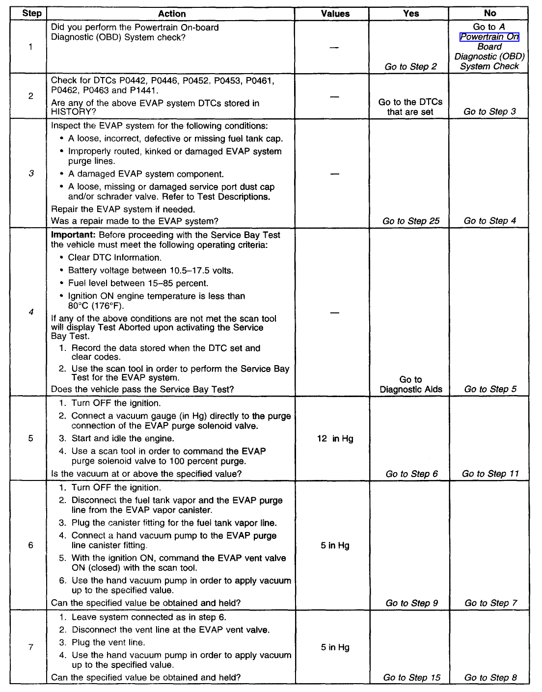
Diagnostic Chart (Part 2 Of 4)
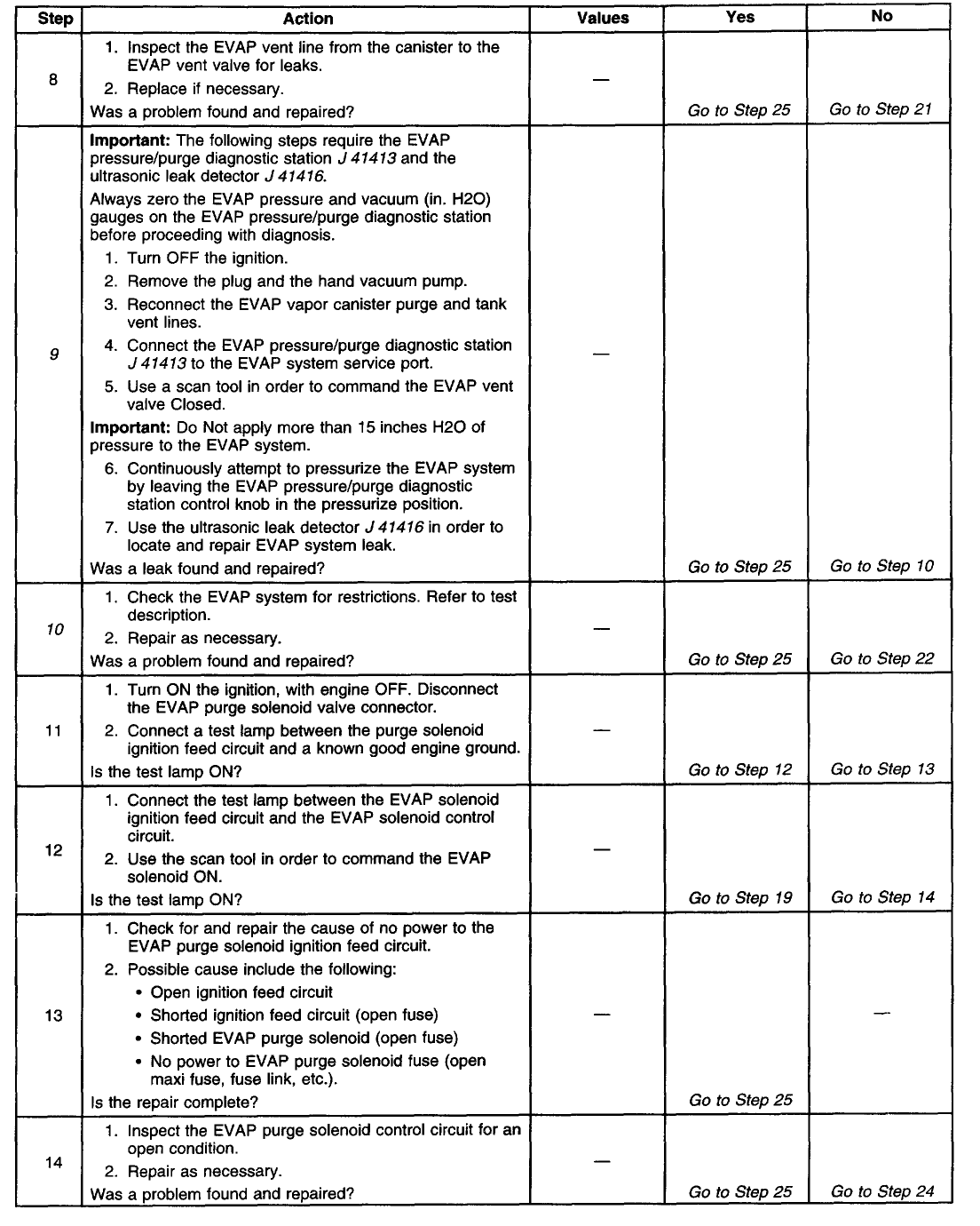
Diagnostic Chart (Part 3 Of 4)
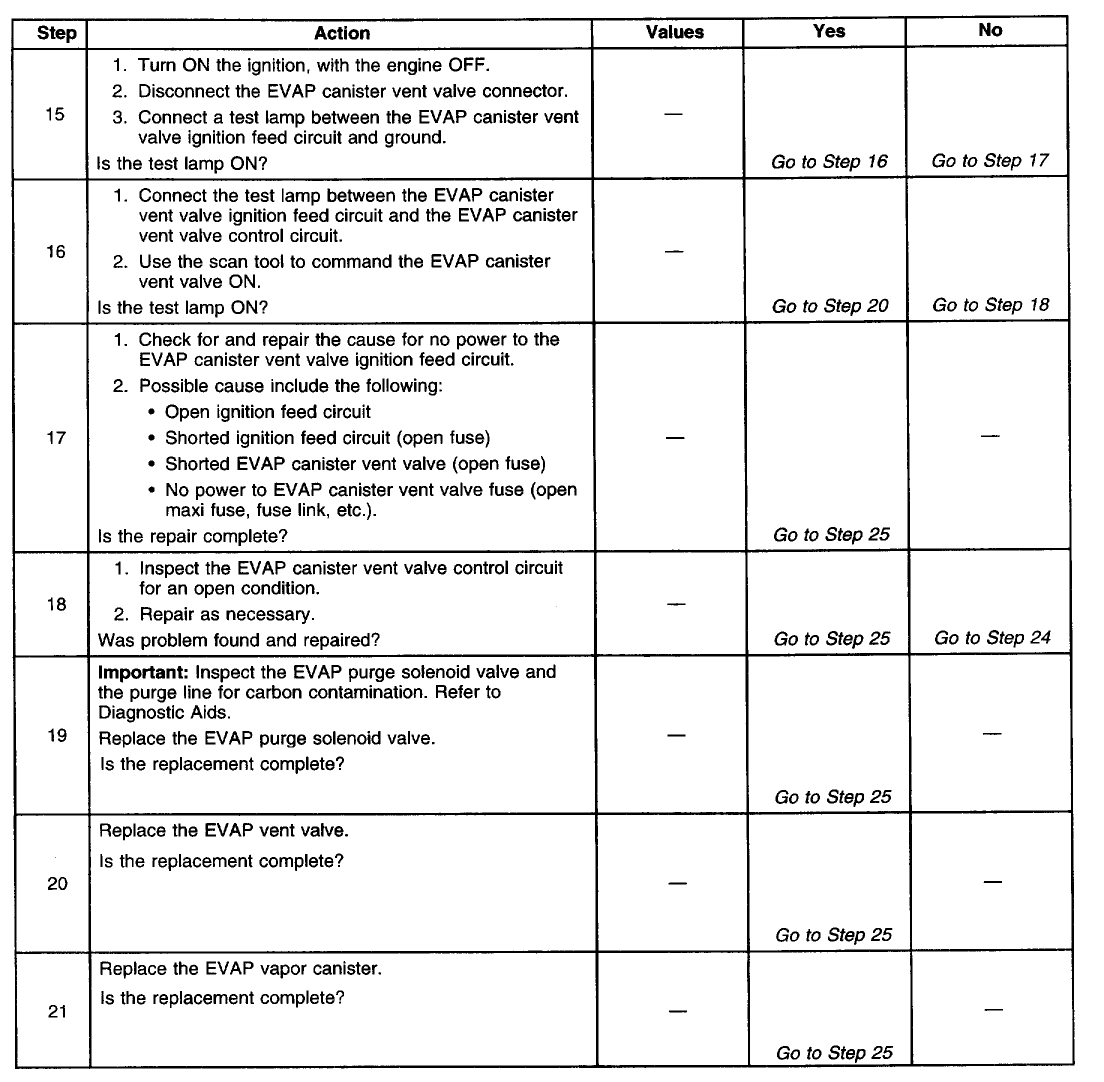
Diagnostic Chart (Part 4 Of 4)
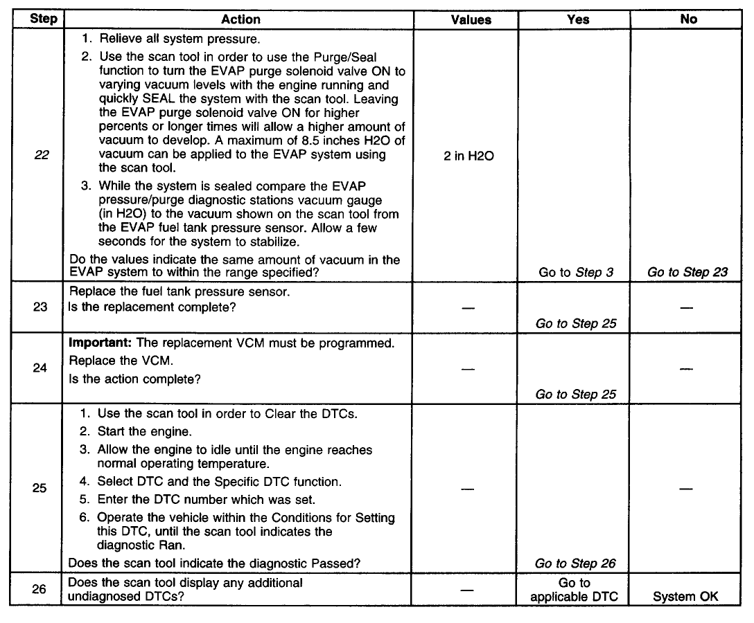
TEST DESCRIPTION
The numbers below refer to the step numbers on the diagnostic table.
3. Inspect the service port. Make sure that the valve core is not damaged. If the service port is suspect of leakage use the following procedure: Disconnect the purge line from the EVAP purge solenoid valve. Connect a hand vacuum pump to the service port by placing the hose/adaptor over the unthreaded end portion of the service port. Apply vacuum to 5 inches Hg. If the vacuum does not hold replace the entire purge line which contains the service port.
4. If the vehicle passes the Service Bay Test then an intermittent leak or restriction had occurred. Check the fuel tank cap for a possible loose or OFF condition that may have caused this DTC to set. If the Service Bay Test can not be run, proceed to step 5. If a fault is not currently present the diagnostic table steps will return you to step 3.
9. Refer to the information supplied with the EVAP pressure/purge diagnostic cart on proper setup and adjustment procedures.
10. With pressure applied it may be necessary to disconnect the EVAP lines at the components to verify that a line or component is not restricted. A restriction would prevent a vacuum (or the step 9 test pressure) from forming in the fuel tank.
22. An EVAP pressure sensor that does not correctly respond to vacuum (or pressure) will cause this DTC to set. The EVAP pressure sensor monitors a range from 7.5 inches
[hr]
P0440
Schematic

CIRCUIT DESCRIPTION
The evaporative system includes the following components:
* The fuel tank
* The EVAP vent solenoid
* The fuel tank pressure sensor
* The fuel pipes and hoses The vapor lines
* The fuel cap
* The evaporative emission canister
* The purge lines
* The EVAP purge solenoid
The evaporative leak detection diagnostic strategy is based on applying a vacuum to the EVAP system and monitoring the vacuum decay rate. The Vehicle Control Module (VCM) monitors the vacuum level via the fuel tank pressure sensor input. At an appropriate time, the EVAP purge solenoid and the EVAP vent solenoid turn ON, allowing the engine vacuum to draw a small vacuum on the entire evaporative emission system. If a sufficient vacuum level cannot be achieved, a large leak or an EVAP system malfunction is indicated. The following conditions can cause this problem:
* A disconnected or malfunctioning fuel tank pressure sensor
* A missing, malfunctioning, improperly installed, or loose fuel cap
* A disconnected, damaged, pinched, or blocked EVAP purge line
* A disconnected or damaged EVAP vent hose
* A disconnected, damaged, pinched, or blocked fuel tank vapor line
* A disconnected or malfunctioning EVAP purge solenoid
* A disconnected or malfunctioning EVAP vent solenoid
* An open ignition feed circuit to the EVAP vent or purge solenoid
* A damaged EVAP canister
* A leaking fuel sender assembly O-ring
* A leaking fuel tank or fuel filler neck
Any of the above conditions can set a DTC P0440.
CONDITIONS FOR RUNNING THE DTC
* No active MAP sensor DTCs
* No active TP sensor DTCs
* No active VS sensor DTCs
* No active O2 sensor DTCs
* No active ECT sensor DTCs
* No active IAT sensor DTCs
* DTC P0125 not active
* The system voltage is between 10-17 volts
* The fuel level is between 12.5-87 percent .
* The ECT is between 4°C-30°C (39°F-86°F)
* The IAT is between 4°C-30°C (39°F-86°F)
* The cold start temperature difference (ECT minus IAT) is less than 1.5°C when the IAT is more than the ECT or 8°C when the ECT is more than the IAT
* The BARO is more than 73 kPa
CONDITIONS FOR SETTING THE DTC
The EVAP system is unable to generate a vacuum more than a calibrated value over a specified period of time.
ACTION TAKEN WHEN THE DTC SETS
* This is a type A DTC that behaves like a B type, in which the VCM illuminates the MIL after the second key cycle.
* The VCM stores the conditions that were present when the DTC sets as a Freeze Frame/Failure Records data.
CONDITIONS FOR CLEARING THE MIL OR DTC
* The control module turns OFF the MIL after 3 consecutive drive trips when the test has run and passed.
* A history DTC will clear if no fault conditions have been detected for 40 warm-up cycles. A warm-up cycle occurs when the coolant temperature has risen 22°C (40°F) from the startup coolant temperature and the engine coolant reaches a temperature that is more than 70°C (158°F) during the same ignition cycle.
* Use a scan tool in order to clear the DTCs.
DIAGNOSTIC AIDS
IMPORTANT: An accurate indication of fuel level is required for the VCM to properly pass or fail this DTC. Always diagnose fuel level sensor DTCs before performing this DTCs diagnostic table. Always check for fuel level sensor DTCs stored in history.
Check for the following conditions:
* A loose, missing, damaged, incorrect or improperly installed fuel cap
* Missing or damaged O-rings at EVAP canister fuel vapor and purge line fittings
* A cracked or punctured EVAP canister
* A damaged or disconnected EVAP purge line, vent hose or fuel tank vapor line
* Incorrectly routed or damaged EVAP system purge and vapor lines
* A poor connection at the VCM. Inspect the harness connectors for the following conditions:
* Backed out terminals
* Improper mating
* Broken locks
* Improperly formed or damaged terminals
* poor terminal to wire connection
* A damaged harness - Inspect the wiring harness to the EVAP vent solenoid, EVAP purge solenoid and the fuel tank pressure sensor for an intermittent, open or short circuit.
* A kinked, pinched or plugged EVAP purge or fuel tank vapor line - Verify that the lines are not restricted.
Refer to Evaporative Emission (EVAP) System Cleaning before starting repairs. Reviewing the Failure Records vehicle mileage since the diagnostic test last failed may help determine how often the condition that caused the DTC to be set occurs. This may assist in diagnosing the condition.
Diagnostic Chart (Part 1 Of 4)

Diagnostic Chart (Part 2 Of 4)

Diagnostic Chart (Part 3 Of 4)

Diagnostic Chart (Part 4 Of 4)

TEST DESCRIPTION
The numbers below refer to the step numbers on the diagnostic table.
3. Inspect the service port. Make sure that the valve core is not damaged. If the service port is suspect of leakage use the following procedure: Disconnect the purge line from the EVAP purge solenoid valve. Connect a hand vacuum pump to the service port by placing the hose/adaptor over the unthreaded end portion of the service port. Apply vacuum to 5 inches Hg. If the vacuum does not hold replace the entire purge line which contains the service port.
4. If the vehicle passes the Service Bay Test then an intermittent leak or restriction had occurred. Check the fuel tank cap for a possible loose or OFF condition that may have caused this DTC to set. If the Service Bay Test can not be run, proceed to step 5. If a fault is not currently present the diagnostic table steps will return you to step 3.
9. Refer to the information supplied with the EVAP pressure/purge diagnostic cart on proper setup and adjustment procedures.
10. With pressure applied it may be necessary to disconnect the EVAP lines at the components to verify that a line or component is not restricted. A restriction would prevent a vacuum (or the step 9 test pressure) from forming in the fuel tank.
22. An EVAP pressure sensor that does not correctly respond to vacuum (or pressure) will cause this DTC to set. The EVAP pressure sensor monitors a range from 7.5 inches
#6
Thanks for the help fellas, I have one more problem that has me puzzled, my heater stopped blowing hot air I replaced the theromstat, flushed the whole system, blew air and water through the heater core nothing stopped up I don't know' the engine temp gauge don't even get hotter than about 150
#7
CF Monarch
Air blockage. The heater core is the highest point in the cooling system and its where the air goes if there is any bubbles in the system. You need to flush the core out with water for a few minutes again and see if that helps, if not, you need to pull a vacuum on the system.
Trending Topics
#9
CF Monarch
No problem. I have to do it to mine too.... lol Since I changed my water pump, my heater hasn't worked and I just have not fixed it.


