
How-to: Adding Cruise Control.

Thread Starter
CF Monarch
Joined: Jul 2007
Posts: 5,891
Likes: 29
From: Princeton, NC, USA
ORIGINAL: AvEoBlue from Club Aveo.
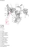
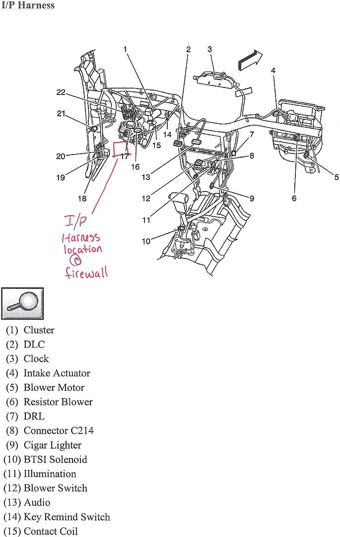
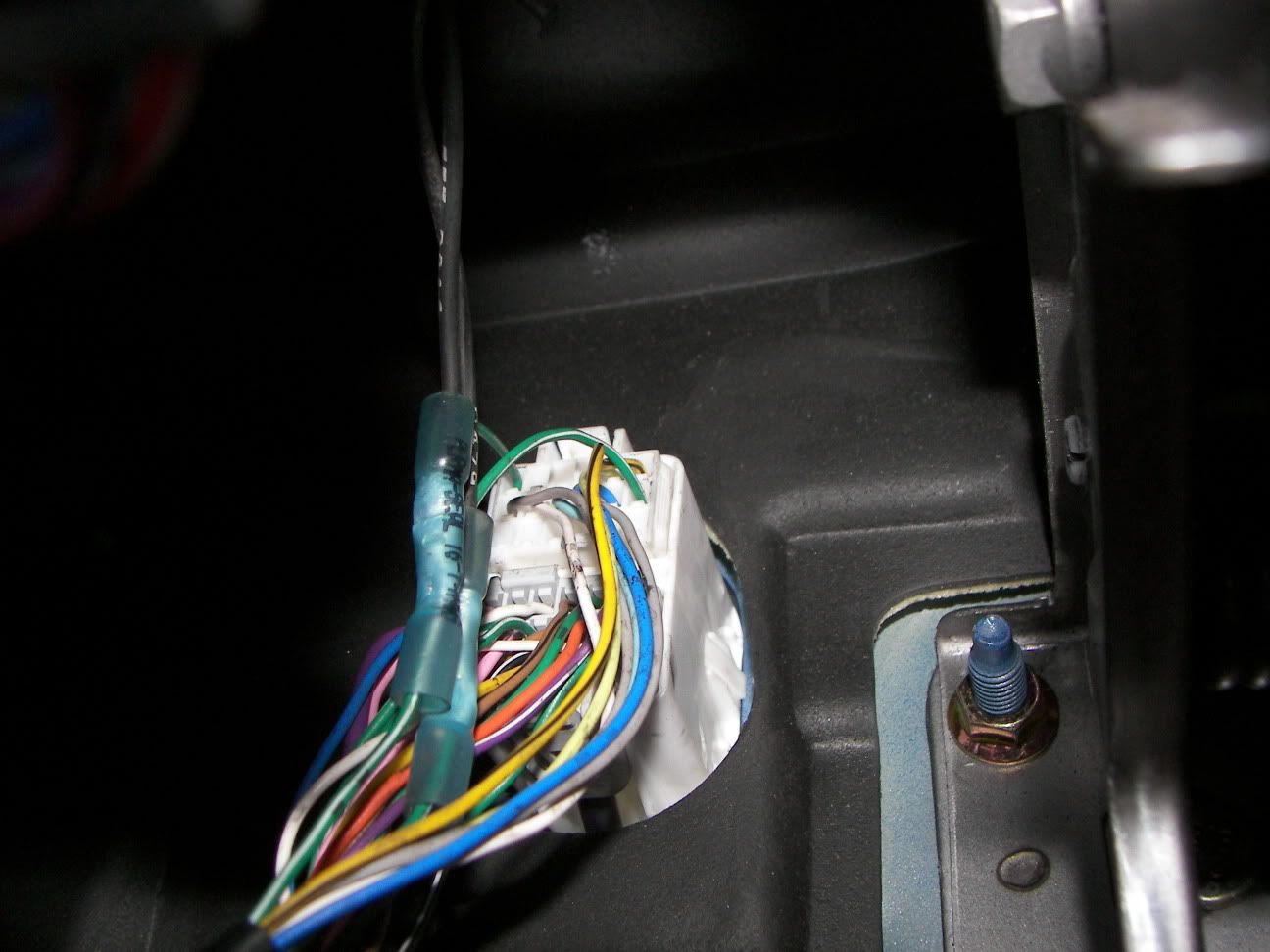
[/align]**Article has been modified from original.**[/align][/align][/align]Rough location of harness to tap in wires.
[/align]
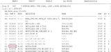
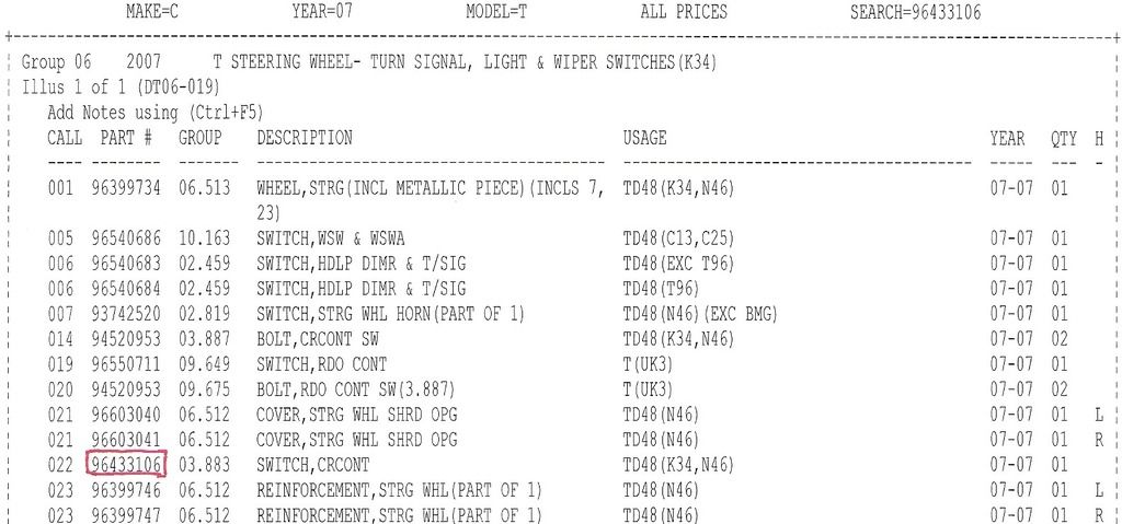
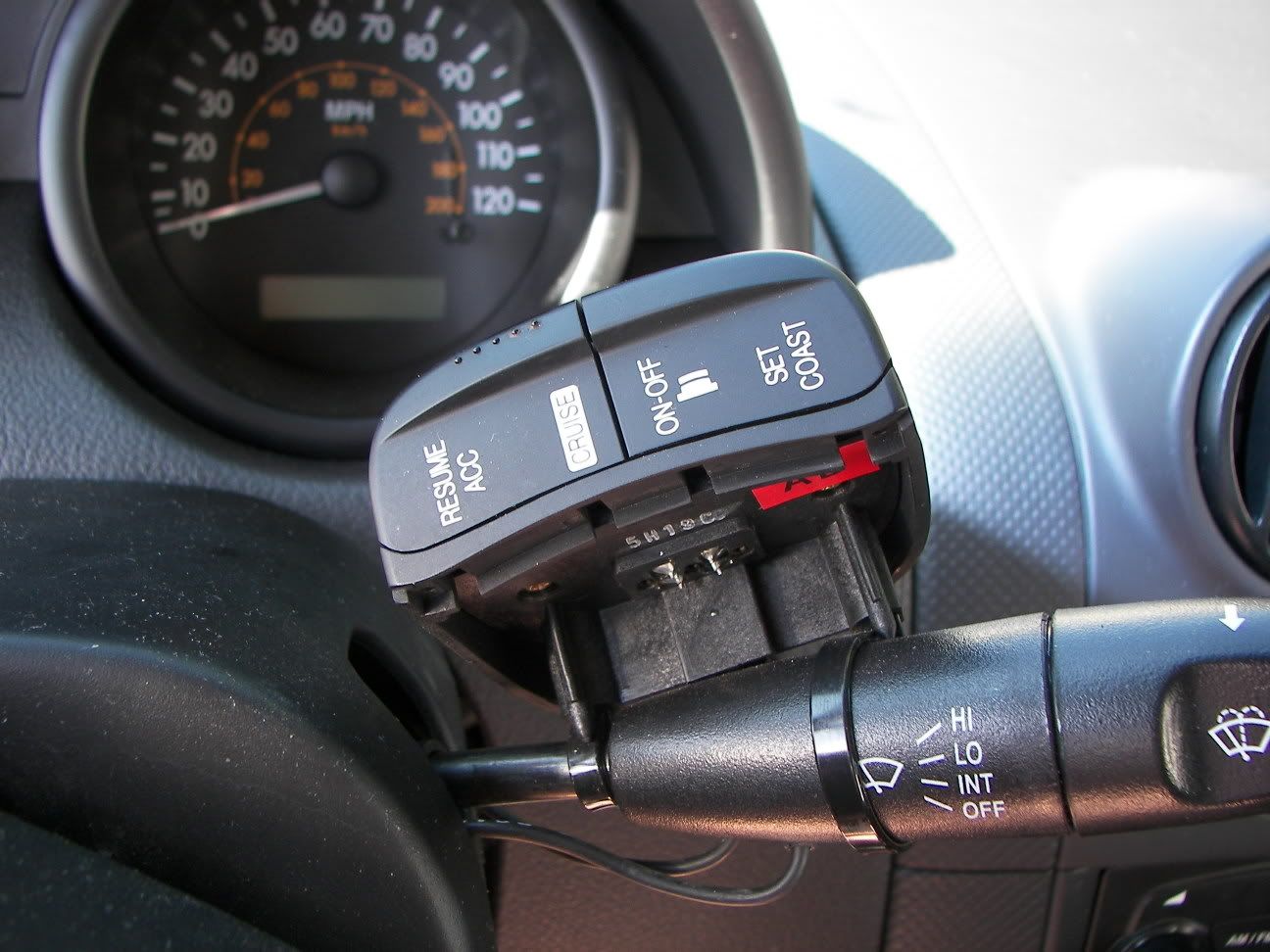
Part Number for switch needed, dealer cost 10.33, list price 18.60
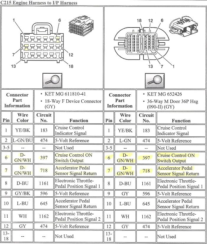
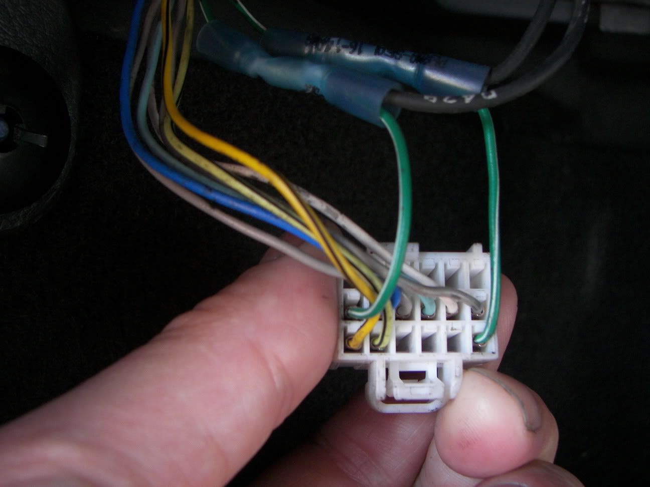
Harness pin out, you will be looking for a firewall pass through with 2 connectors, one white, one Grey. You want the white one. splice 1 lead off pin 6, dark green with a white stripe, and another wire lead off pin 7, dark green with a white stripe.
 [/align][/align][/align][/align]
 [/align]
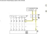
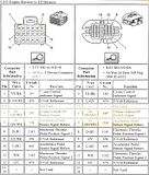
Here is how the circuit ties into the accelerator pedal.
Here is the picture of the "I/P" connector.
 [/align][/align]
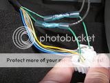 [/align]
[/align]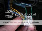
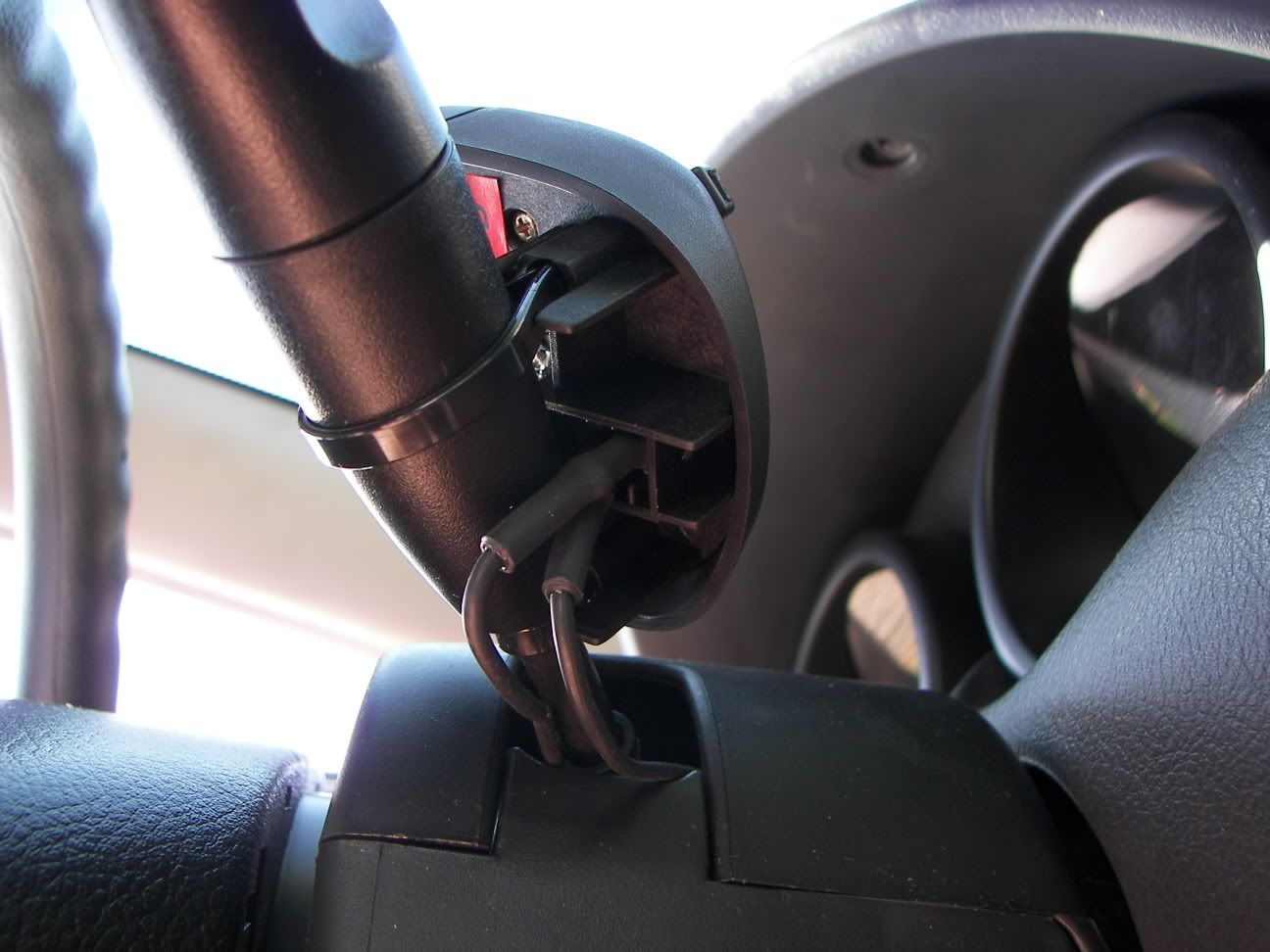
THIS IS A TEMPRORARY MOUNT. The only mounting I can come up with the switch for now, until my warranty runs out. Its a quick disconnect.[/align][/align]

The switch will have a 4-pin connector. You will need to use the 2 outside pins for it to work. I used some non-insulated female terminal ends for this, I used some heat shrink around the terminals when done to prevent any connection between any other pins. IT DOES NOT MATTER WHICH WAY YOU HOOK THE WIRES UP ON THE SWITCH END. I've tried both combinations, they work the same.
[/align]
Part Number for switch needed, dealer cost 10.33, list price 18.60
Harness pin out, you will be looking for a firewall pass through with 2 connectors, one white, one Grey. You want the white one. splice 1 lead off pin 6, dark green with a white stripe, and another wire lead off pin 7, dark green with a white stripe.
 [/align][/align][/align][/align]
 [/align]
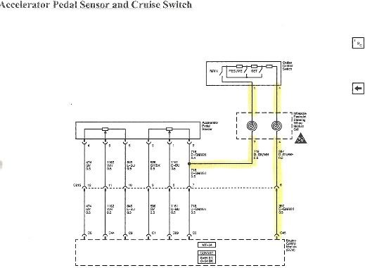
Here is how the circuit ties into the accelerator pedal.
Here is the picture of the "I/P" connector.
 [/align][/align]
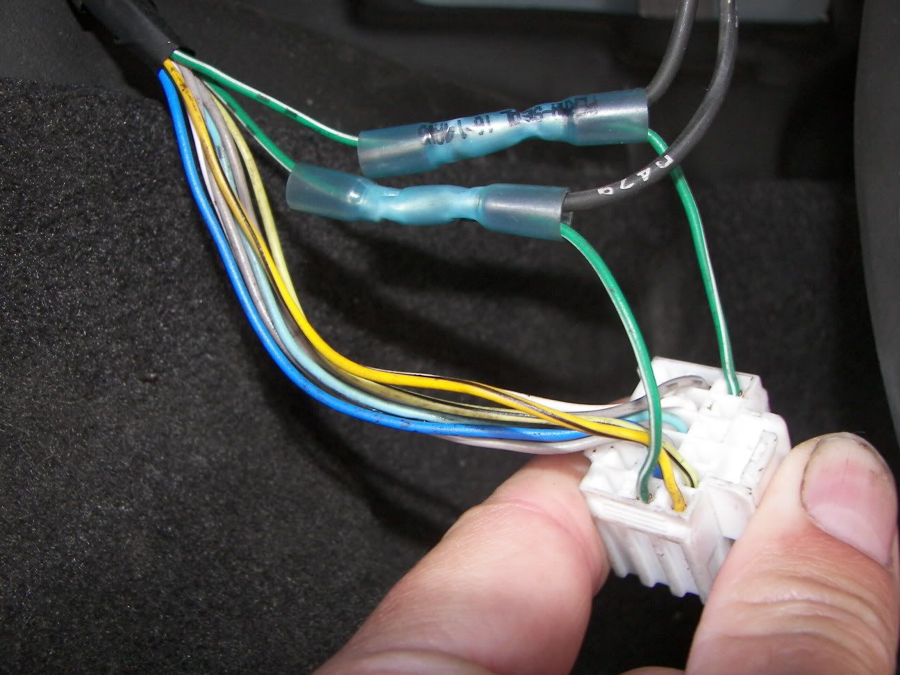 [/align]
[/align]
THIS IS A TEMPRORARY MOUNT. The only mounting I can come up with the switch for now, until my warranty runs out. Its a quick disconnect.[/align][/align]
The switch will have a 4-pin connector. You will need to use the 2 outside pins for it to work. I used some non-insulated female terminal ends for this, I used some heat shrink around the terminals when done to prevent any connection between any other pins. IT DOES NOT MATTER WHICH WAY YOU HOOK THE WIRES UP ON THE SWITCH END. I've tried both combinations, they work the same.

Thread Starter
CF Monarch
Joined: Jul 2007
Posts: 5,891
Likes: 29
From: Princeton, NC, USA
ORIGINAL: Monzaveo
Was yours an SVM model? I tried this today on my '06 Exactly as described above.
I double checked all connections, but it dosent seem to work.
Was yours an SVM model? I tried this today on my '06 Exactly as described above.
I double checked all connections, but it dosent seem to work.

CF Beginner
Joined: Nov 2008
Posts: 6
Likes: 0
Ok I got mine to work.
After alot of trial and error, and thinking I got a bunk switch, I figured it out.
On my switch the 2 outside pins dont do anything (3 & 4 of '1234'). I tried pins 1 and 3 however, and it works as shown. So the pin configuration may be different on some of the switches.
After alot of trial and error, and thinking I got a bunk switch, I figured it out.
On my switch the 2 outside pins dont do anything (3 & 4 of '1234'). I tried pins 1 and 3 however, and it works as shown. So the pin configuration may be different on some of the switches.
CF Beginner
Joined: Nov 2008
Posts: 6
Likes: 0
The 96433106 from the sheet.
I brought that number right to the dealer. It looks exactly like the one in the pics.
Also its pins 1 and 4 that get mine working. not 1 and 3 like I mentioned previously.
The dealership said there were none local when I ordered it and it had to come from california.
I brought that number right to the dealer. It looks exactly like the one in the pics.
Also its pins 1 and 4 that get mine working. not 1 and 3 like I mentioned previously.
The dealership said there were none local when I ordered it and it had to come from california.
Trending Topics


CF Beginner
Joined: May 2011
Posts: 1
Likes: 0
Hello, my name is Fernando, From ARgentina. My regards to ALL at the forum.
I have an Mexico AVEO LTAT (2011) and I have sent a lot of time in the setup of the crusie control.
I buyed an Rostra KIT 250-9000 but it no don work.
I cheked the pin 45 voltaje, as Rostra says. And HAve 5V off, 3.7V on 2.7 V Set, 2.3 Resume. but it do not work!!!.
I want to know if those Voltajes are correct at PIN 45 and if anyone knows if CC may be disabled by GM at ECU software.
Thanks ALL
Fernando
Argentina
Sorry my poor english