Chevrolet Silverado 1999-2006: How to Replace Lower Control Arm
Your Silverado's control arms will eventually wear out, and depending on how much stress you put your truck through, wearing out might come sooner rather than later. This article walks you through the steps and tasks required to change your Chevy Silverado's lower control arms.
This article applies to the Chevrolet Silverado 1500 GMT800 (1999-2006).
A Chevy Silverado truck that exhibits a strong shake in the steering wheel while turning, or creates a thumping or squeaking noise from the front suspension may be suffering from a worn out lower control arm. Generally, this occurs with the arm bushings or ball joint wearing out as well. Lower control arm bushings can be replaced using a bushing removal tool/bushing press. Bushing removal kits can be rented from an auto supply store, and often at no cost to a customer. However, if the ball joint has failed, the lower control arm needs to be replaced because this ball joint is not serviceable.

Materials Needed
- 14, 15, 18, 21, 22, 24, and 35mm sockets
- Ratchet and extension
- 21mm box wrench
- 18 and 21mm long, open-end (box) wrench
- Large locking pliers (Vice Grips)
- Spray paint (bright color)
- Marker or paint stick
- Torque wrench
- Hydraulic floor jack and jack stands
- Grease and grease gun
- Hammer (big)
- Pry bar
- Reciprocating saw (optional, it depends on the age and condition of the vehicle)
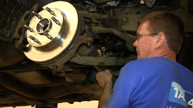
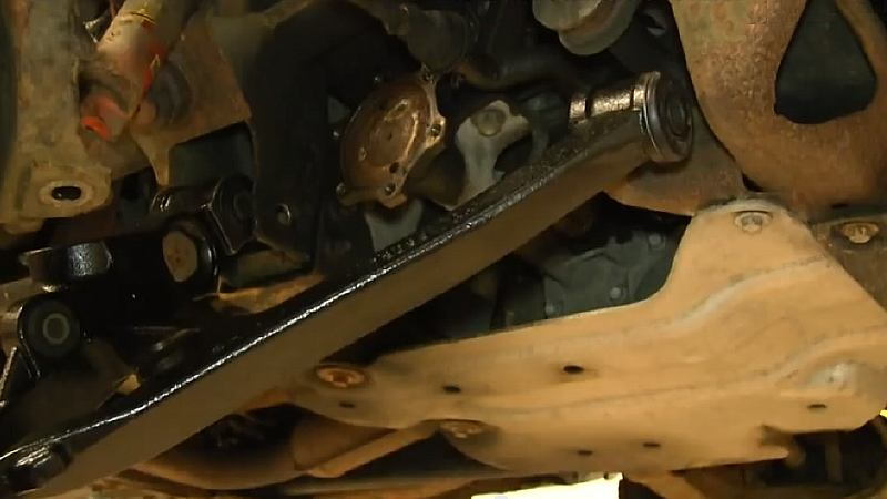
Traditional "wishbone"-type, "A"-shaped front suspensions utilize an upper and lower control arm. While the upper arm handles wheel alignment issues (camber and caster), the lower control arm handles most of the heavy lifting. And instead of using coil springs for front support, this generation of Silverado trucks use a torsion bar suspension (one on each side).
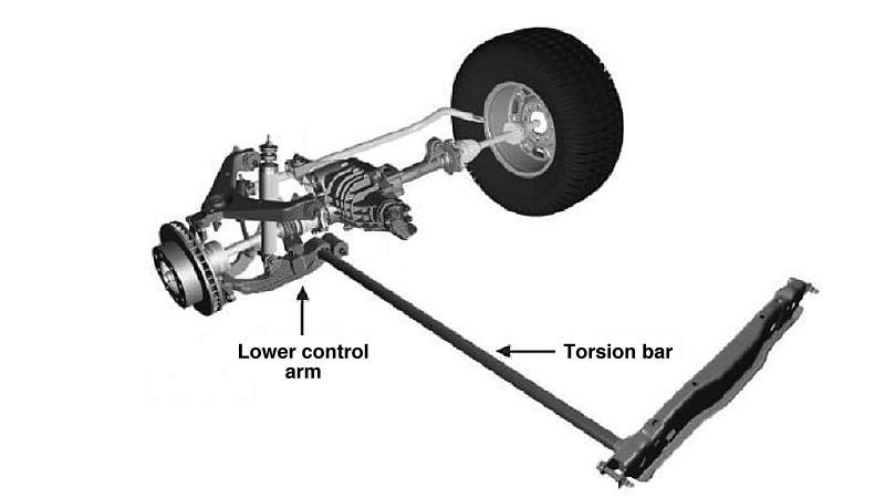
Torsion bars are long round bars made from spring steel mounted along the frame rails. The front of the bar attaches to a pivot point in the lower control arm, and the back end is secured to a lever called a “torsion key.” The two torsion keys are held in a support crossmember. The ride height of the front is set by “winding up” the rear of the bar until its tension forces the lower control arm up a sufficient amount to hold the weight of the vehicle’s front end at the proper ride height. Minor height changes are accomplished with an adjusting bolt that pushes up against a lever on the torsion key.
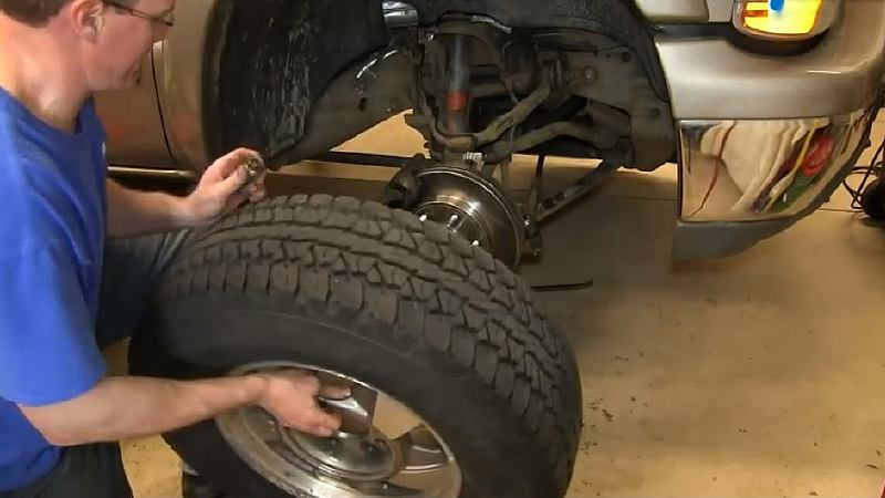
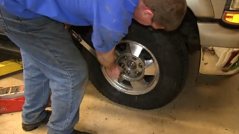
Step 1 – Raise the truck's front end and remove the front wheel
- Before starting, put your truck on level pavement, set the emergency brake, and chock the rear tires to prevent the truck from rolling backwards.
- Remove the hub cap, and break the wheel's lug nuts loose.
- Then remove the center dust cap, and break the 35mm axle nut loose. Don’t remove any of the nuts just yet.
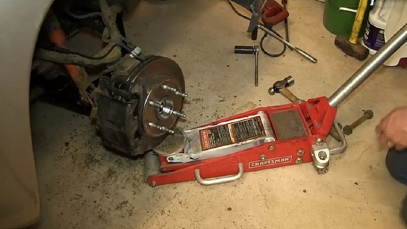
- Using a floor jack, raise the front of the vehicle and place jack stands under the frame rails just behind the lower control arm mounts.
- Lower the truck onto the jack stands, making sure the stands are not tilting in any direction.
- With the vehicle in the air, remove the lug nuts to take the front tire and wheel off.
(Related Article: How to Jack Up Your Truck - ChevroletForum.com)
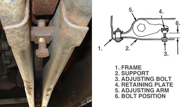
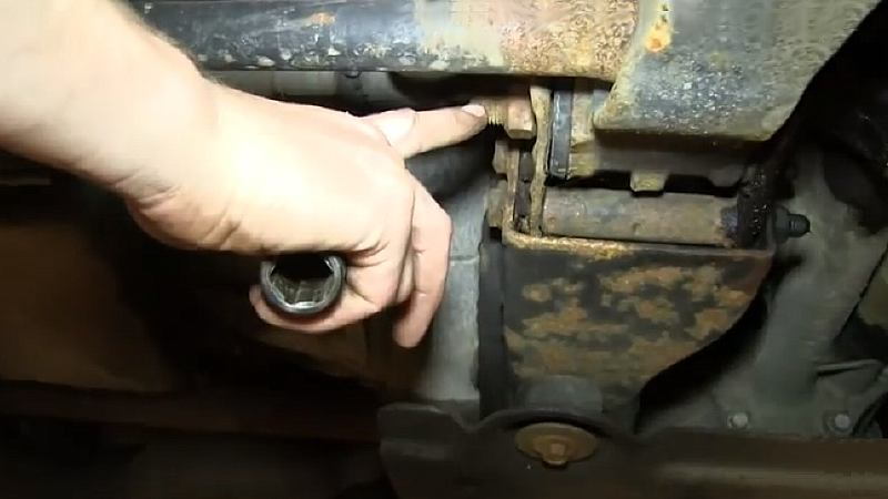
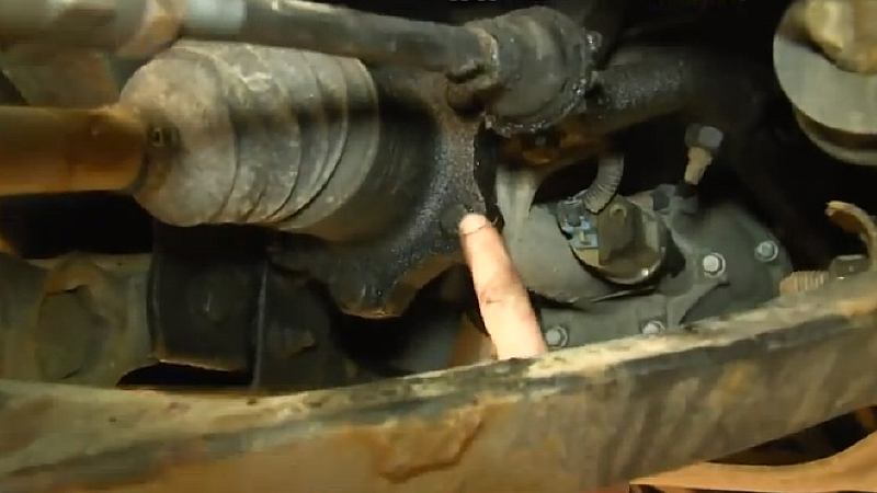
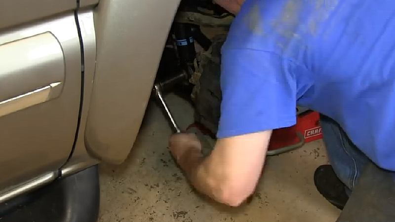
Step 2 – Spray-paint threads of the torsion key adjusting bolt
- With bright spray paint, spray the torsion key adjusting bolt in the center supper crossmember. Painting the bolt will allow you to tighten it back to its original position later.
- After the paint has fully dried, loosen the bolt that's pushing up the lever on the torsion key until the bolt is resting on the retaining plate. Don’t remove the bolt.

Pro Tip
The vehicle’s front end needs to be raised for this operation in order to relax the suspension; otherwise, the bolt will strongly resist being turned.
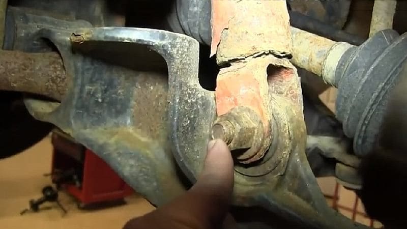
Step 3 – Loosen nut holding ball joint to the wheel knuckle
- With tension now removed from the torsion bar, loosen the 24mm nut at the bottom of the wheel knuckle that holds the lower control arm ball joint in place.
- Don’t remove the nut, but leave a large gap between the nut and the wheel knuckle.

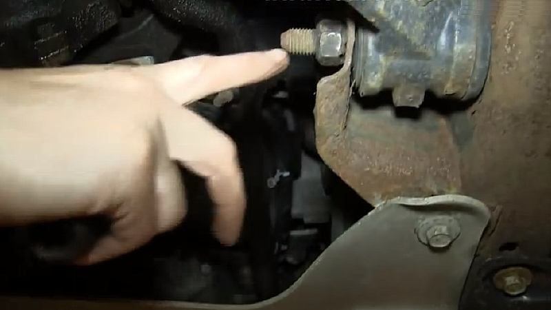
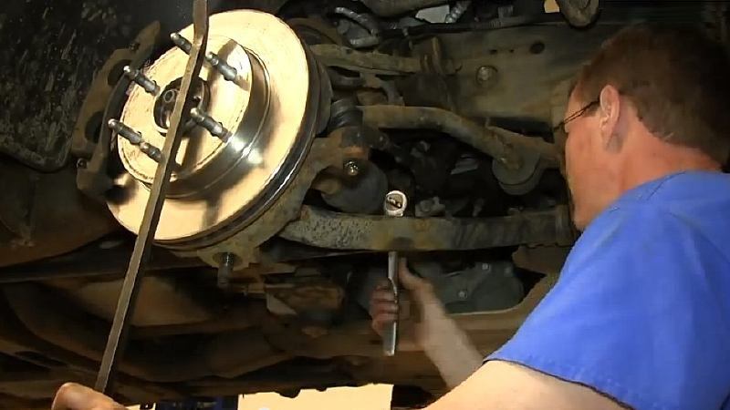
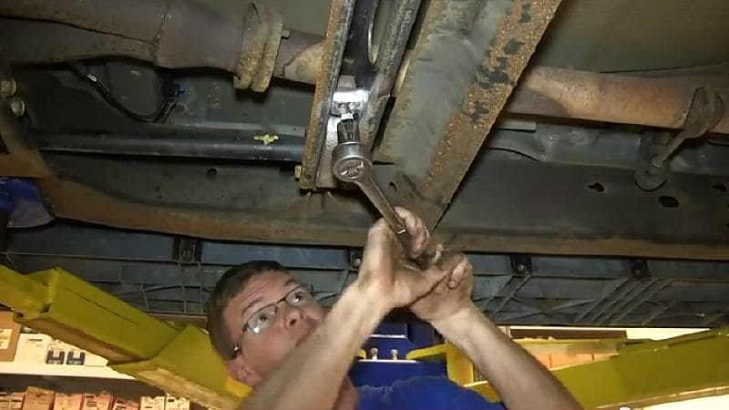
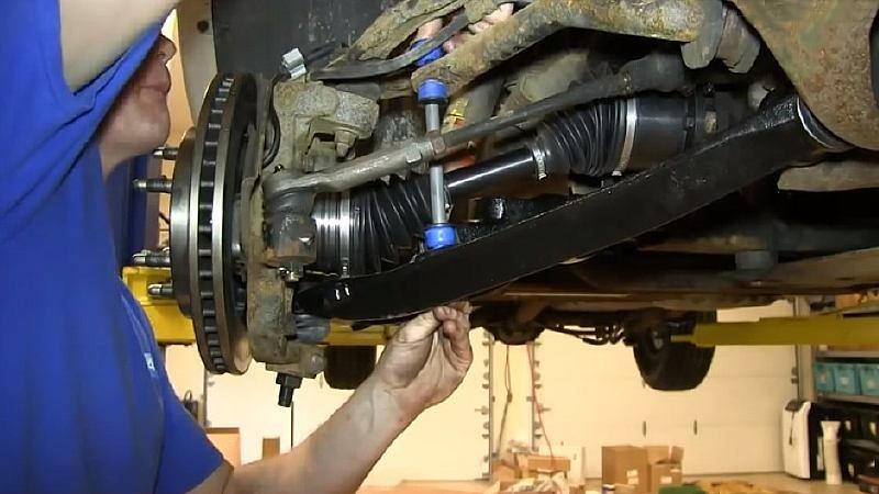
Step 4 – Loosen nuts on the lower control arm fastener bolts
- Loosen the two 24mm nuts that hold the lower control arm bushings to their attachment brackets. You may have to use a box wrench to hold the 22mm bolt heads and remove the nuts.
- Note that the forward bolt head is accessible from a cut-out on the front crossmember. Remove the nuts and washers, but don’t remove the 22mm bolts just yet.
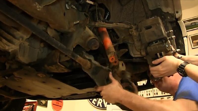
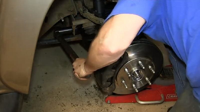
Step 5 – Remove stabilizer link between the lower control arm and stabilizer bar
- The stabilizer link connects the stabilizer bar to the lower control arm. Use the locking pliers (Vice Grips) to lock onto the nut at the top end of the stabilizer link.
- Then remove the 14mm bolt from the bottom of the control arm. When it runs up against the rotor, the locking pliers will stop the nut at the top from turning, allowing you to unscrew the bolt.

Note
If the link bolt can’t be removed from the lower control arm, remove the nut, the spacer, and all of the grommets for now. Refer to Step 8.
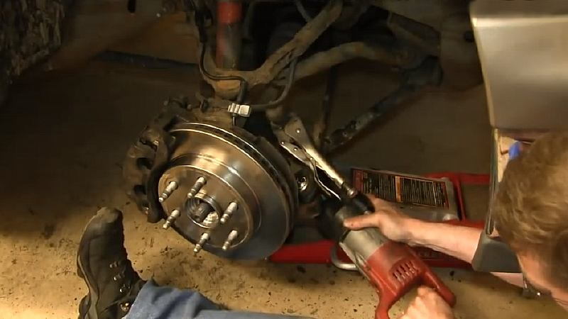
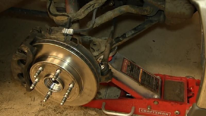
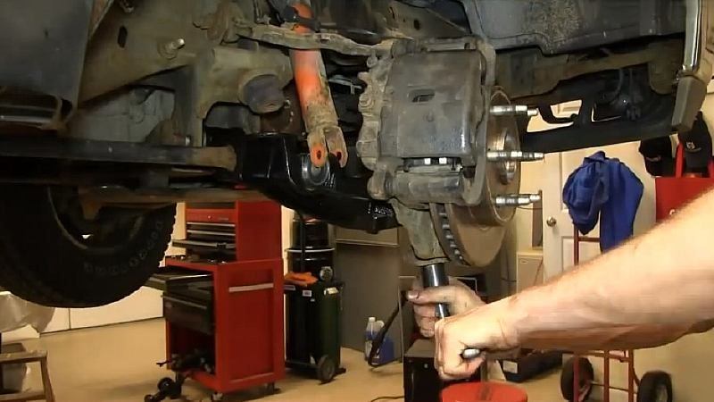
Step 6 – Remove the shock absorber bottom attachment bolt
- First jack up the lower control arm at the point where it connects to the wheel knuckle.
- Raise it enough to release the downward pressure from the shock absorber.

- Remove the 21mm nut that holds the bottom of the shock absorber to the rear of the lower control arm
- Then slide out the 21mm bolt.
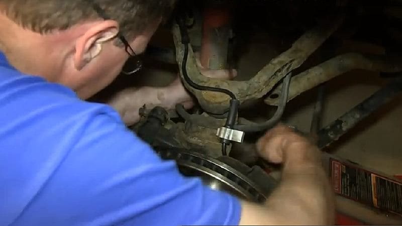
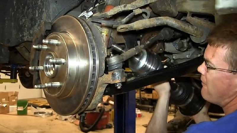
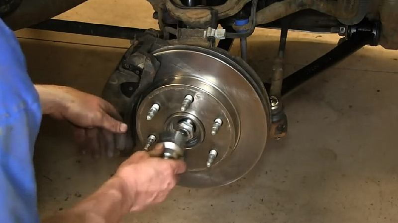
Step 7 – Separate lower control arm ball joint from the wheel knuckle
- Make sure the 24mm nut at the bottom of the wheel knuckle, which holds the lower control arm ball joint to the knuckle, is loose but still in place.
- Re-position the trolley jack to where it’s just underneath this nut.
- Then apply upward pressure on the nut with the jack.

- With a big hammer, pound the back of the wheel knuckle until the threaded stud on the lower control arm's ball joint breaks free from the knuckle.

Step 8 – Remove the wheel nut, stabilizer link, and front axle shaft
- Re-position the trolley jack, again putting it under the lower control arm, and raise it to release downward pressure off of the wheel.
- Remove the already-loosened 24mm nut at the bottom of the wheel knuckle. This nut holds the lower control arm ball joint to the knuckle via its threaded stud.
- With the jack still in place, remove the 35mm wheel nut and the washer behind it from the center of the hub. If you aren’t using air tools, you’ll need someone to apply the brakes when you remove this nut to keep the wheel from spinning.
- Now remove the stabilizer link from the lower control arm. If it refuses to come out, you may have to cut off the stabilizer link shaft with a reciprocating saw.
- Replace the stabilizer link assembly with a new one when you install the new lower control arm.
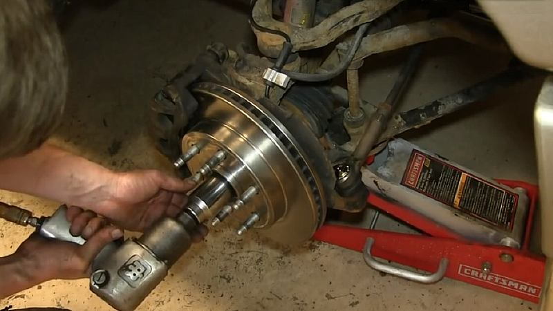
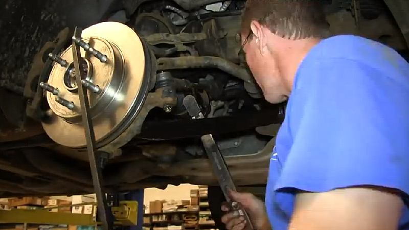
- Remove the six bolts that attach the wheel’s axle shaft and constant velocity (CV) joint to the front axle. Be careful not to rip the rubber boot.
- Hold a pry bar against the hub in between the lug bolts to loosen and remove each of the 15mm bolts. Spin the wheel to access each bolt.
- Hammer the side of the wheel axle shaft to break it free.
- Then pull the shaft straight back and out of the wheel, then set it aside.
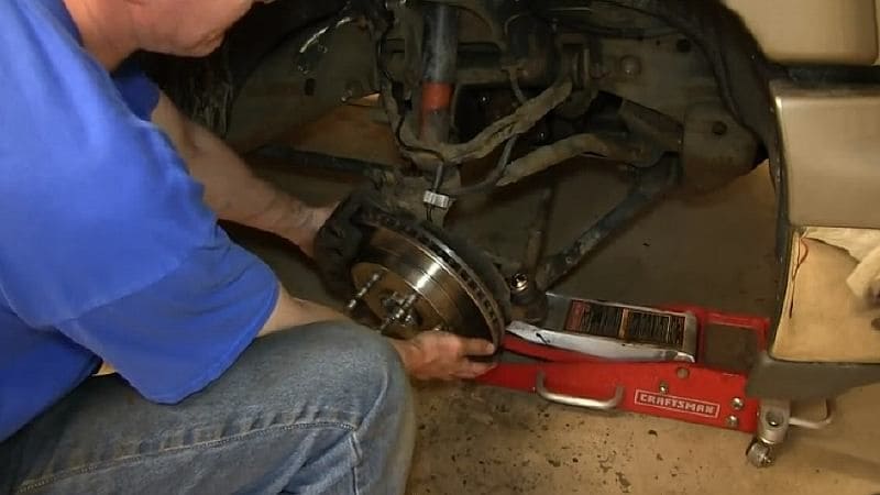
Step 9 – Free and remove the lower control arm
- Push the bottom of the shock absorber out of its lower control arm attachment point.
- Using the floor jack, raise the lower control arm until the knuckle is free from the threaded stud of the lower control arm’s ball joint.
- While lifting up the wheel knuckle, lower the jack, and then pull the wheel knuckle out and away from the lower control arm.
- Remove the two attachment bolts at the back of the lower control arm.
- With the wheel knuckle tied off or held out of the way, mark a point on the torsion bar shaft and the old lower control arm so you can match it up with the new control arm. Use a marking pen or paint stick.
Note
The new lower control arm will need to be attached to the torsion bar in the same relative position as the old one—not rotated higher or lower—to ensure the same suspension lift.

- Pull the lower control arm forward and off the end where it's attached to the torsion bar.
Step 10 – Install the new lower control arm
- Remove any loose rust from the attachment end of the torsion bar.
- Then, using the marks on the end of the torsion bar as a guide, attach the new control arm to the torsion bar in the same position as the old one.
- Replace the lower control arms into the attachment brackets, and fasten the bolts back in place.
- Replace the two washers and nuts, but only hand-tighten them for now.

- Using the floor jack to lift the front of the lower control arm. Raise it enough to insert the new ball joint's threaded stud into the attachment hole of the wheel knuckle.
- Then lower down the jack.
- Now move the floor jack underneath the knuckle, and raise the wheel up to the point where you can replace the 24mm nut holding the ball joint to the knuckle.
- Tighten this nut to factory specifications.
- Feed the axle shaft back into the wheel.
- Then fasten the six 15mm bolts that attach the wheel’s drive shaft and CV joint to the front axle.
- Holding a pry bar between the lug bolts again, spin the rotor to access each 15mm bolt.
- Torque each bolt to 65 ft-lbs (88 N-m).
- Place the stabilizer link back into its attachment point on the lower control arm.
- With a washer and grommet on the bottom, feed the shaft through the attachment hole in the lower control arm, and then put it through the hole.
- Add another grommet and washer, and then the tube.
- Then add another washer and grommet.
- Lastly, through the sway bar attachment hole, add another grommet and washer, and then hand-tighten the nut. You may need to use the trolley jack to lift the bottom of the control arm and get the nut back on top of the link shaft. Do not fully tighten the nut just yet.

- Re-tighten the adjustment bolt in the torque tube back to its original position. Use the paint as a guide for where you need to stop when tightening down the bolt.
- Fasten the lower bolt, washer, and nut to the shock absorber, and tighten it to factory specifications.
- Place the floor jack under the wheel knuckle, and lift it up to a point where its tire would be contacting the road.
- Then tighten the two 24mm nuts that secure the lower control arm yokes to the two 22mm bolts. Tighten the nuts to factory specifications.
- With the wheel still in its road-height position, tighten down the stabilizer link nut from the top and the bottom so that the bushings are close to the same width as the washers.
- Re-install the 35mm washer and wheel nut, and tighten it down to factory specifications. Again, without an air wrench, be sure to have someone apply the brakes as you tighten this nut.
- Put the wheel back on and hand-tighten the lug nuts.
- Then lower the vehicle, and torque the lug nuts in a crossing-pattern to 100 ft-lbs (136 N-m).
- With the wheel on the ground, torque the 35mm wheel nut down to 160 ft-lbs (217 N-m).
- Snap the dust cap that covers the wheel nut back into place.
- And finally, replace the hub cap or lug cover.
Featured Video: How to Replace Lower Control Arm
Related Discussion
- 2004 Silverado Arm Ball Joints - ChevroletForum.com