When you click on links to various merchants on this site and make a purchase, this can result in this site earning a commission. Affiliate programs and affiliations include, but are not limited to, the eBay Partner Network.
Hi all. Posting here because the internals of my Chevrolet Workhorse p30 are very similar to those of an Express Van 1400 year 2010.
Its a 4.3 v6 vortec with 4l80e tramsmission, was working on the alternator, cs130, pins marked as P L I S. The wiring was looking sketchy and the alternator would not charge the battery, so I researched the web and connected S ouput to the alternator out screw where the big red wire goes out to the battery and the L pin was wired with a lamp/bulb of 350 Ohm to an ignition voltage source. P and I not connected. Light bulb goes on on the key turn and goes out when the engine is running.
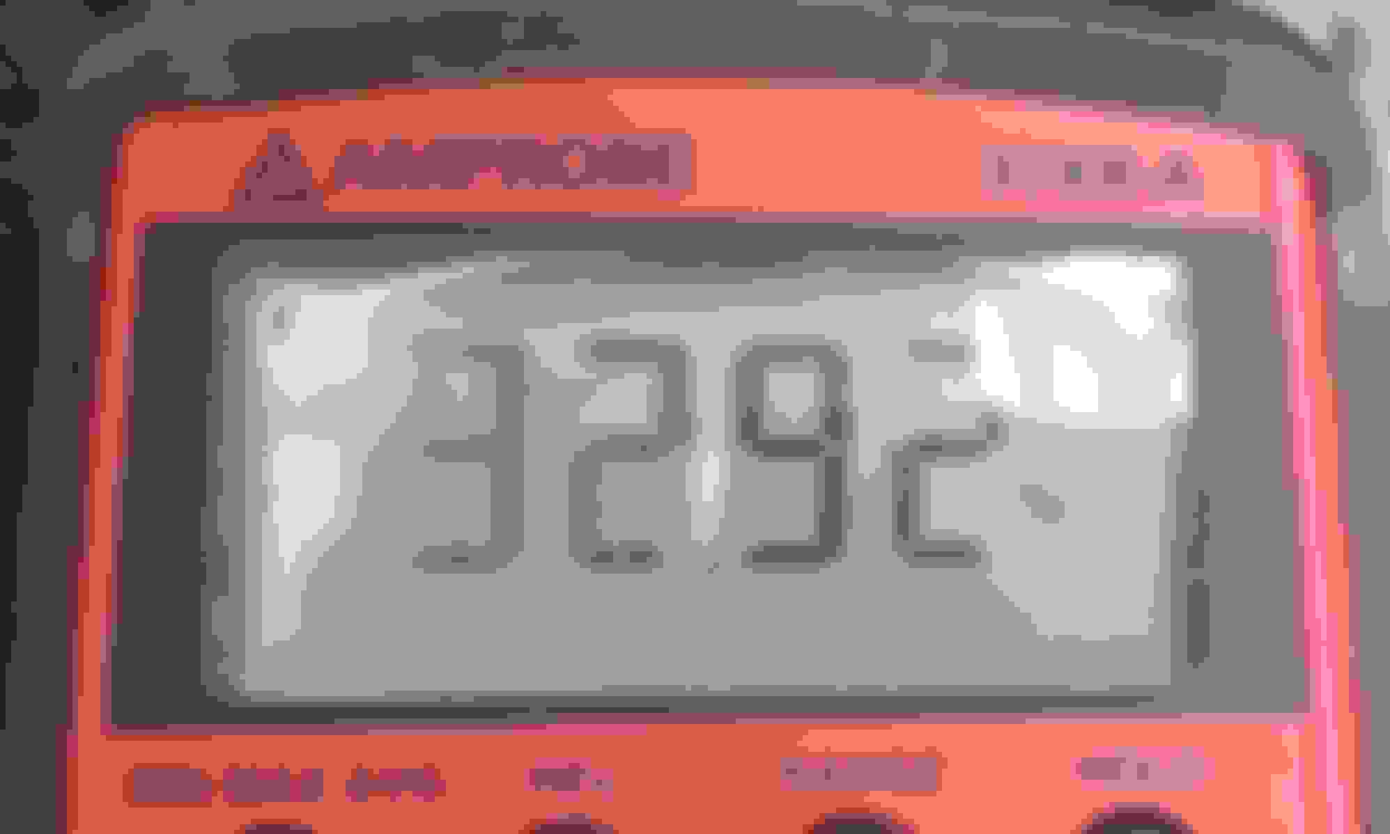
Dmm measured 14v across battery terminals.
The engine was idling for about 30 minutes, I was hoping observe the alternator to stop charging the battery. What is the charging voltage cutoff for the CS130? I dont want to kill my new battery by overcharging. What measurements can I perform, what else can I check?
The alternato wasnt charging at first, I ve checked the wiring as I have previously explained (L and S pins) and now it is charging.
My worry now is "will it stop charging or overcharge the battery to death"
I had the engine idling for a while expecting charge cutoff. Maybe I had to give it more time, idk.
What if the voltage regulator circuit is not working properly and needs replacement, is there any test I can perform to see if it stops charging?
not sure if you have the same "issue" i had when i first got my 2010 silverado. i thought the alt was going out as when you first start it up it would put out 14v but after driving it 10+ minutes and cruising down the road the batter gauge would drop to 12-13 or so volts. came on here inquiring about it and its a "smart" charge designed to not overheat the battery and try to save some MPGs by limiting how much the alternator works. its supposed to charge at a low voltage when the demand for volt isnt high
Yes gm uses smart charging circuitry now with various charging modes. Not sure what year it was implemented though. I’m guessing around 2008. Since you have so many pins on your alt then you probably do. Your owners manual might say.
having said that, cars still worked fine before smart charging, when they only had constant voltage regulators. The thing is, lead acid batteries are somewhat self-tapering which makes them simple to charge. As their charge increases, their internal resistance goes up, so charging current automatically tapers off.
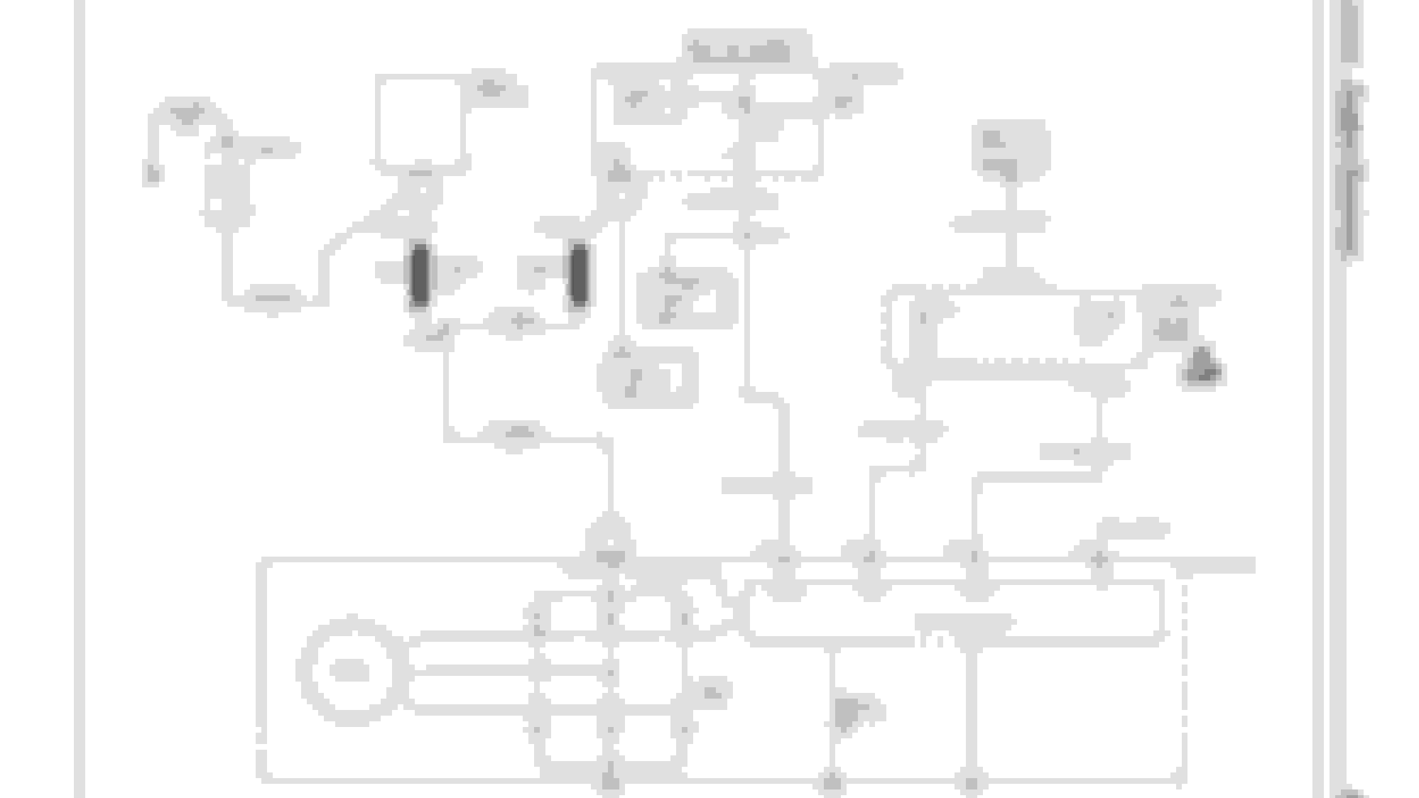
After reading some more about the CS130 and hook ups and checking several diagrams and schematics I have found this one
The harness near the alternator has a 3 pin connector with 2 wires, both red in color one thicker than the other, I guess the thick one is Batt+ for S (sense) DMM read +12.28v the other one appears to be for F/I (field) input, probing it with a DMM for Hz and % (duty cycle) I got this with ignition ON and engine not running
I proceded to hook the alternator as in the schematic, with the Light, Field and Sense and ran the engine for about 30 mins at idle speeds.
The voltage across the battery was 14.7v 'ish at the beginning and got to about 14.11v after half an hour. Frequency showed 1.643kHz and duty cycle ranged in the 50's %.
Should this indicate that the alternator is operating properly?
I would like to learn how to read those schematic such as the one at the beginning of the post.
I have downloaded the service manuals from workhorse.navistar.com/Default.aspx?tabid=574 and they cover many versions on engine configuration with gas ones from 4.3L to 8.1L including diesel ones too. This schematic was on the page 4111 from "Secci�n 6 engines" for a year 2000 Workhorse.
Nothing wrong at 14.7 volts. My K-1500 runs a solid 14.5 volts,

 February 6th, 2020, 7:35 PM