Wiper problems on a 98
#1
Well of course we are setting all kinds of record rain fall here is Massachusetts! and timing is everything right!, so my wipers only run of FULL SPEED. The intermittent settings and slow settings are not working. WHen I shut off the high speed setting the wipers pretty much stop right where I tunr off the wipers, and do not settle to the down position.
My research has led me here to this pulse module. Where is the ground that i should be checking? is there an actual ground wire from the wiper motor to the fire wall? I'd like to confirm this is working before I spedn the #30.00 for the new pulse motor.
thanks for any assistance that can be shared!
Gary
#2
***created new thread for this because the thread this was attached to was outdated and fragmented.***
There are problems with the cold soldered boards on the wiper motors... Mine do that occasionally, so I really have not addressed it yet.
This fix also applies to incomplete wipe cycle (where they stop halfway on either the upward stroke or the return stroke.
There are problems with the cold soldered boards on the wiper motors... Mine do that occasionally, so I really have not addressed it yet.
This fix also applies to incomplete wipe cycle (where they stop halfway on either the upward stroke or the return stroke.
Originally Posted by swartlkk
Do your wipers have a mind of their own? Do they choose when to start and when/where to stop? If so, your problem is likely caused by cold solders on the PCB (printed circuit board) in the wiper motor itself. Some have "fixed" this by placing a wadded up piece of cardboard between the wiper motor and the electrical connection, but this is only a temporary fix. There are many imaginative "fixes" for this problem. One certain repair job is to resolder the joints at fault.
Required Tools:
T20 Torx bit and driver
Soldering iron and solder
15 minutes of your time (time may vary depending on experience)
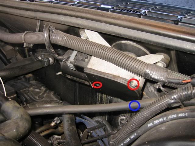
The wiper motor is on the firewall to the left of the brake booster as shown in the image below. Start by disconnecting the electrical connection to the wiper motor. You will want to remove the two T20 screws that are circled in red, then loosen, but do not remove the T20 screw circled in blue. This screw can be a challenge to put back in if completely removed and the cover can be removed without completely removing this screw.

Once you have the cover off, it is time to remove the circuit board. The only thing holding the circuit board in at this point is the electrical connection to the wiper motor itself. These connections are down on the lower left of the circuit board. An accurately placed flat blade screw driver will assist in prying the board loose. Place the tip of the screw driver between the circuit board and the motor and gently pry up on the board. It shouldn't take much force at all to remove it.
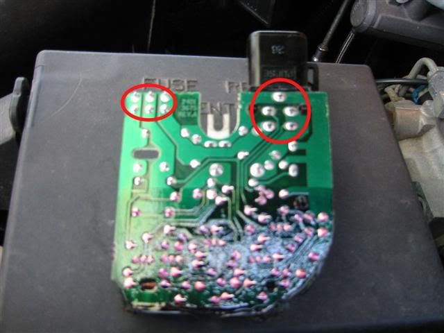
Now that the board is out, you can have a look at it. By far the most common location for the affected solder joints is where the main electrical connection is made to the board. This location is circled on the right in the picture below. I have seen cracks in the connections to the wiper motor itself before as well, shown circled on the left of the picture below.

To repair the solder joints, simply heat the joint back up to reflow the solder. If necessary, add some more solder to the joint to make it stronger. One key to soldering is to keep the joint from moving while the solder is cooling. Any movement in the joint while the solder is solidifying will weaken the joint and cause the problem to reoccur.
With the circuit board repaired, you can reassemble it into the wiper motor assembly. But before doing so, take a look at the grease inside. If it is dried out, now would be a good time to clean things up and replace the grease. A non-conductive grease should be used so as not to short out the circuit board. Most general purpose lithium based grease is non-conductive, but it is worth mentioning.
Reassemble the reverse of disassembly.
Give it a try! If everything works as it should, pat yourself on the back for a job well done!
Required Tools:
T20 Torx bit and driver
Soldering iron and solder
15 minutes of your time (time may vary depending on experience)
The wiper motor is on the firewall to the left of the brake booster as shown in the image below. Start by disconnecting the electrical connection to the wiper motor. You will want to remove the two T20 screws that are circled in red, then loosen, but do not remove the T20 screw circled in blue. This screw can be a challenge to put back in if completely removed and the cover can be removed without completely removing this screw.

Once you have the cover off, it is time to remove the circuit board. The only thing holding the circuit board in at this point is the electrical connection to the wiper motor itself. These connections are down on the lower left of the circuit board. An accurately placed flat blade screw driver will assist in prying the board loose. Place the tip of the screw driver between the circuit board and the motor and gently pry up on the board. It shouldn't take much force at all to remove it.
Now that the board is out, you can have a look at it. By far the most common location for the affected solder joints is where the main electrical connection is made to the board. This location is circled on the right in the picture below. I have seen cracks in the connections to the wiper motor itself before as well, shown circled on the left of the picture below.

To repair the solder joints, simply heat the joint back up to reflow the solder. If necessary, add some more solder to the joint to make it stronger. One key to soldering is to keep the joint from moving while the solder is cooling. Any movement in the joint while the solder is solidifying will weaken the joint and cause the problem to reoccur.
With the circuit board repaired, you can reassemble it into the wiper motor assembly. But before doing so, take a look at the grease inside. If it is dried out, now would be a good time to clean things up and replace the grease. A non-conductive grease should be used so as not to short out the circuit board. Most general purpose lithium based grease is non-conductive, but it is worth mentioning.
Reassemble the reverse of disassembly.
Give it a try! If everything works as it should, pat yourself on the back for a job well done!
#3
Thanks Brent for the detailed service instructions. Now my decision is whether to do the soldering job and possibly save myself $30.00 + labor time, or do I spend the $30.00 and simply swap out the module all together. I'l,l be sure to post up my results which I will do over the next day or 2.
I do appreciate the tips and how too's!
Wish me luck brother!
Gary
I do appreciate the tips and how too's!
Wish me luck brother!
Gary
Thread
Thread Starter
Forum
Replies
Last Post
ruley73
Equinox & Terrain
21
September 15th, 2017 9:11 AM


