

 July 22nd, 2015, 10:24 AM
Last edit by: IB Advertising
See related guides and technical advice from our community experts:
- Chevrolet Silverado 1999-2006 GMT800 How to Install Trailer Brake Controller
Step by step instructions for do-it-yourself repairs.

Factory brake controller...DIY?
April 16th, 2013, 6:02 PM
#11
CF Junior Member

Join Date: Mar 2013
Posts: 80
Likes: 0
Received 0 Likes
on
0 Posts
#07-08-45-001F: Procedure for Installation of an Aftermarket Trailer Brake Controller - (Nov 9, 2010)
Subject: Procedure for Installation of an Aftermarket Trailer Brake Controller
Models: 2007-2011 Cadillac Escalade, Escalade ESV, Escalade EXT
2007-2011 Chevrolet Avalanche, Silverado, Suburban, Tahoe
2007-2011 GMC Sierra, Yukon, Yukon Denali, Yukon XL, Yukon Denali XL
2008-2010 HUMMER H2
with Integrated Trailer Brake Controller
--------------------------------------------------------------------------------
This bulletin is being revised to combine information from bulletins 06-08-45-008D and 07-08-45-001E. Please discard Corporate Bulletin Numbers 07-08-45-001E and 06-08-45-008D (Section 08 - Body and Accessories).
--------------------------------------------------------------------------------
Important: Installation of an electric brake controller and the wiring connections outlined in this bulletin are the responsibility of the dealership or customer. These repairs should never be charged to warranty. If you have any questions, please consult with your District Service Manager.
Some customers may request to have an aftermarket trailer brake controller added to their vehicle, OR in lieu of the factory integrated trailer brake controller (ITBC) (RPO JL1).
Installation Instructions
Starting with the new 2007 full-size utilities and pickups and 2008 HUMMER H2, there is no longer an electric trailer brake controller pigtail harness.
To install an aftermarket trailer brake controller, use the four blunt cut wires located near the data link connector.
The following steps should be used to complete the installation.
Four Blunt Cut Wires
Dark Blue
Circuit 47
Brake Signal to Trailer Connector
Red/Black
Circuit 242
Battery Power
Light Blue/White
Circuit 6311
Brake Switch Input
White
Circuit 22
Ground
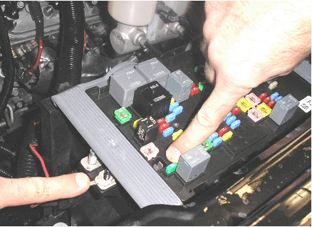
Important: Ensure that the ringlets are not interfering with the UBEC cover.
�Place the terminal on the larger of the two studs at the front of the electrical center and secure with an M8 nut. This is circuit #242 to stud #2, to power the aftermarket trailer brake controller.
Important: The fuse is already present in the vehicle to power the electrical trailer brake controller system.
�ONLY For Vehicles Equipped with JL1 - Locate connector X126 or X115 (varies with vehicle build; refer to SI) near the underhood fuse block. Refer to SI Document ID# 1849049 - I/P Harness-Engine Compartment. Circuit 47 from the blunt cut wires near the data link connector will end at connector X126 terminal "G" or X115 terminal "B5." Obtain enough Dark Blue 12 gauge wire to run from X126/X115 to the 7-way trailer connector at the bumper. On one end of the Dark Blue wire attach terminal part number 15304732, located in Delphi Tray 8 and insert into X126 "G" or terminal part number 15304720 located in Delphi Tray 19 and insert into X115 "B5." Run the Dark Blue wire in its own conduit along the frame to the 7-way trailer connector at the bumper. Remove circuit 47 from the 7-way trailer connector terminal "C" and tape the bare terminal and attach to the harness. Attach terminal part number 12110853, located in Delphi Tray 4, to the other end of the Dark Blue wire and insert it into the 7-way trailer connector terminal "C."
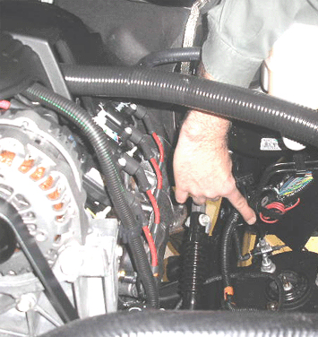
�ONLY For Vehicles Equipped with JL1 - The Red/Black wire, circuit 242, must be connected to stud #2 of the 30 Amp fuse of the underhood fuse block. This wire is located between the left fender and the underhood fuse block.
Important: This procedure will not result in any trailer brake related display messages to be set. However, ITBC diagnostics will continue to function. If an ITBC fault is detected, a "Service Trailer Brake System" message will be displayed on the driver information center (DIC) and an appropriate DTC will be stored in the ITBC module. The operator will still be able to adjust gain and access the "Trailer Gain / Output" display page in the DIC. However, the factory installed ITBC system will not sense a trailer connection and will not provide output to the trailer.
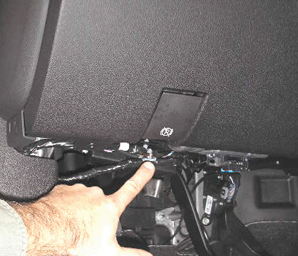
�Locate the trailer brake control circuits that are looped and taped to the main harness under the instrument panel.
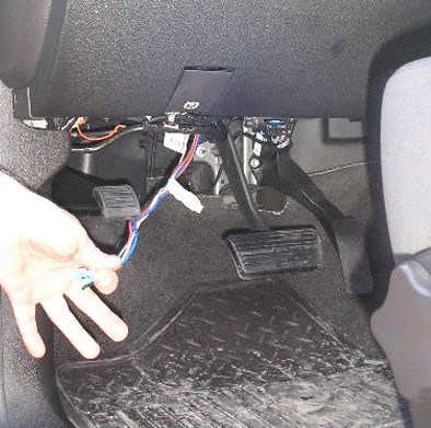
�Pull the trailering wire harness down.
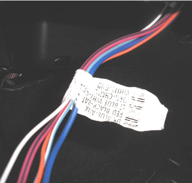
�Match the vehicle harness label circuit functions to the trailer brake controller jumper harness functions.
Important: The color or wires to be joined together may not match.
� Dark Blue Wire: switched power from controller to trailer brakes
� Red with Black Stripe: fused vehicle power to electrical brake controller
� Light Blue with White Stripe: Brake switch input to power electric brake controller
� White: ground
� Orange: CHMSL (Center High Mounted Stop Lamp) -- not required with most systems
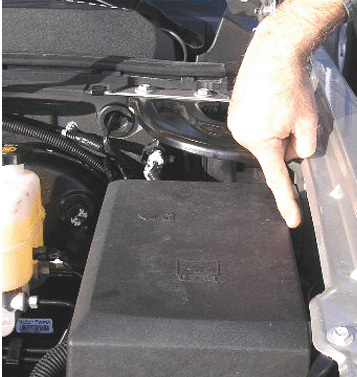
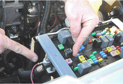
�After completing the under dash connections to the electric brake controller, open the hood and locate the red wire that is taped to the harness between the underhood electrical center and the driver side front fender.
�Break the tape on the red/black wire and pull it toward the front of vehicle.
�Remove the lid from the electrical center.
Auxiliary Power (Applies to All LD and 2007-2009 HD's Only) Without JL1
Circuit #742 for Auxiliary Power at the 7-way trailer connector is no longer connected by the GM Assembly Plant. If the customer desires auxiliary power at the trailer connector location (i.e. refrigeration, battery charger or interior light in the trailer), complete the following steps to connect circuit #742:
�Locate the red/black wire, looped and taped to the chassis harness, below the brake master cylinder.
�Break the tape and route the wire to the front of the underhood electrical center.
Important: Ensure that the ringlets are not interfering with the UBEC cover.
�Place the terminal on the smaller of the two studs on the electrical center and secure with an M6 fastener. This is circuit #742 to stud #1 for auxiliary power to the 7-way trailer connector.
�ONLY for vehicles without RPO TP2 - Auxiliary Battery, install a 40 amp fuse to power the circuit.
Important: For vehicles equipped with RPO TP2 -- Devices powered by this fuse will drain the vehicle battery if left connected with the vehicle not running.
Warranty Information
This installation procedure is to be performed at the customer's request and at their expense. It is not a warranty repair and a claim should not be submitted for reimbursement.
GM bulletins are intended for use by professional technicians, NOT a ""do-it-yourselfer"". They are written to inform these technicians of conditions that may occur on some vehicles, or to provide information that could assist in the proper service of a vehicle. Properly trained technicians have the equipment, tools, safety instructions, and know-how to do a job properly and safely. If a condition is described, DO NOT assume that the bulletin applies to your vehicle, or that your vehicle will have that condition. See your GM dealer for information on whether your vehicle may benefit from the information.
WE SUPPORT VOLUNTARY TECHNICIAN CERTIFICATION
Subject: Procedure for Installation of an Aftermarket Trailer Brake Controller
Models: 2007-2011 Cadillac Escalade, Escalade ESV, Escalade EXT
2007-2011 Chevrolet Avalanche, Silverado, Suburban, Tahoe
2007-2011 GMC Sierra, Yukon, Yukon Denali, Yukon XL, Yukon Denali XL
2008-2010 HUMMER H2
with Integrated Trailer Brake Controller
--------------------------------------------------------------------------------
This bulletin is being revised to combine information from bulletins 06-08-45-008D and 07-08-45-001E. Please discard Corporate Bulletin Numbers 07-08-45-001E and 06-08-45-008D (Section 08 - Body and Accessories).
--------------------------------------------------------------------------------
Important: Installation of an electric brake controller and the wiring connections outlined in this bulletin are the responsibility of the dealership or customer. These repairs should never be charged to warranty. If you have any questions, please consult with your District Service Manager.
Some customers may request to have an aftermarket trailer brake controller added to their vehicle, OR in lieu of the factory integrated trailer brake controller (ITBC) (RPO JL1).
Installation Instructions
Starting with the new 2007 full-size utilities and pickups and 2008 HUMMER H2, there is no longer an electric trailer brake controller pigtail harness.
To install an aftermarket trailer brake controller, use the four blunt cut wires located near the data link connector.
The following steps should be used to complete the installation.
Four Blunt Cut Wires
Dark Blue
Circuit 47
Brake Signal to Trailer Connector
Red/Black
Circuit 242
Battery Power
Light Blue/White
Circuit 6311
Brake Switch Input
White
Circuit 22
Ground

Important: Ensure that the ringlets are not interfering with the UBEC cover.
�Place the terminal on the larger of the two studs at the front of the electrical center and secure with an M8 nut. This is circuit #242 to stud #2, to power the aftermarket trailer brake controller.
Important: The fuse is already present in the vehicle to power the electrical trailer brake controller system.
�ONLY For Vehicles Equipped with JL1 - Locate connector X126 or X115 (varies with vehicle build; refer to SI) near the underhood fuse block. Refer to SI Document ID# 1849049 - I/P Harness-Engine Compartment. Circuit 47 from the blunt cut wires near the data link connector will end at connector X126 terminal "G" or X115 terminal "B5." Obtain enough Dark Blue 12 gauge wire to run from X126/X115 to the 7-way trailer connector at the bumper. On one end of the Dark Blue wire attach terminal part number 15304732, located in Delphi Tray 8 and insert into X126 "G" or terminal part number 15304720 located in Delphi Tray 19 and insert into X115 "B5." Run the Dark Blue wire in its own conduit along the frame to the 7-way trailer connector at the bumper. Remove circuit 47 from the 7-way trailer connector terminal "C" and tape the bare terminal and attach to the harness. Attach terminal part number 12110853, located in Delphi Tray 4, to the other end of the Dark Blue wire and insert it into the 7-way trailer connector terminal "C."
�ONLY For Vehicles Equipped with JL1 - The Red/Black wire, circuit 242, must be connected to stud #2 of the 30 Amp fuse of the underhood fuse block. This wire is located between the left fender and the underhood fuse block.
Important: This procedure will not result in any trailer brake related display messages to be set. However, ITBC diagnostics will continue to function. If an ITBC fault is detected, a "Service Trailer Brake System" message will be displayed on the driver information center (DIC) and an appropriate DTC will be stored in the ITBC module. The operator will still be able to adjust gain and access the "Trailer Gain / Output" display page in the DIC. However, the factory installed ITBC system will not sense a trailer connection and will not provide output to the trailer.

�Locate the trailer brake control circuits that are looped and taped to the main harness under the instrument panel.

�Pull the trailering wire harness down.

�Match the vehicle harness label circuit functions to the trailer brake controller jumper harness functions.
Important: The color or wires to be joined together may not match.
� Dark Blue Wire: switched power from controller to trailer brakes
� Red with Black Stripe: fused vehicle power to electrical brake controller
� Light Blue with White Stripe: Brake switch input to power electric brake controller
� White: ground
� Orange: CHMSL (Center High Mounted Stop Lamp) -- not required with most systems

�After completing the under dash connections to the electric brake controller, open the hood and locate the red wire that is taped to the harness between the underhood electrical center and the driver side front fender.
�Break the tape on the red/black wire and pull it toward the front of vehicle.
�Remove the lid from the electrical center.
Auxiliary Power (Applies to All LD and 2007-2009 HD's Only) Without JL1

Circuit #742 for Auxiliary Power at the 7-way trailer connector is no longer connected by the GM Assembly Plant. If the customer desires auxiliary power at the trailer connector location (i.e. refrigeration, battery charger or interior light in the trailer), complete the following steps to connect circuit #742:
�Locate the red/black wire, looped and taped to the chassis harness, below the brake master cylinder.
�Break the tape and route the wire to the front of the underhood electrical center.

Important: Ensure that the ringlets are not interfering with the UBEC cover.
�Place the terminal on the smaller of the two studs on the electrical center and secure with an M6 fastener. This is circuit #742 to stud #1 for auxiliary power to the 7-way trailer connector.
�ONLY for vehicles without RPO TP2 - Auxiliary Battery, install a 40 amp fuse to power the circuit.
Important: For vehicles equipped with RPO TP2 -- Devices powered by this fuse will drain the vehicle battery if left connected with the vehicle not running.
Warranty Information
This installation procedure is to be performed at the customer's request and at their expense. It is not a warranty repair and a claim should not be submitted for reimbursement.
GM bulletins are intended for use by professional technicians, NOT a ""do-it-yourselfer"". They are written to inform these technicians of conditions that may occur on some vehicles, or to provide information that could assist in the proper service of a vehicle. Properly trained technicians have the equipment, tools, safety instructions, and know-how to do a job properly and safely. If a condition is described, DO NOT assume that the bulletin applies to your vehicle, or that your vehicle will have that condition. See your GM dealer for information on whether your vehicle may benefit from the information.
WE SUPPORT VOLUNTARY TECHNICIAN CERTIFICATION
 April 16th, 2013, 6:15 PM
#12
CF Junior Member
Join Date: Mar 2013
Posts: 80
Likes: 0
Received 0 Likes
on
0 Posts
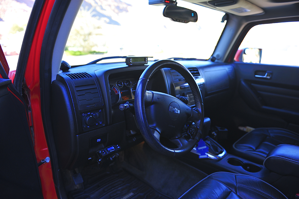
From personal experience wiring a brake controller to a Hummer H3 it was simply splicing the wires from the aftermarket controller (Tekonsha P3) to the H3's wiring harness under the dash. I did not have to do any of the underhood connections as shown in the bulletin. I mounted the controller to the left of the steering column and it works GREAT.
You can just see it hanging off the bottom left of the lower dash, next to the steering wheel. (MAKE SURE TO NOTE THAT THE WIRE COLORS FROM THE VEHICLE DO NOT MATCH IDENTICALLY TO THE CONTROLLER WIRES; THEY USE DIFFERENT COLORS.)
It is a proportional controller in that it senses how fast the deceleration is and applies proportional voltage to the electric trailer brakes. The greater the voltage, the harder the brakes are applied.
It works, and works very well...
Brake Controllers - Tekonsha
Now, when it came to my Silverado, I did not want to mount something under the dash. (My truck came with the HD trailer tow package and no controller...). So I purchased a remote controller. Sounds strange, but it works as good as the interior mounted controller, and NO need to mount anything under the dash, no need to splice wires.
It is installed onto the trailer frame, and the 7-pin plug from the trailer connects to the controller and the wiring harness, from the controller, with the 7-pin connector then connects to the vehicle's trailer plug.
It is also a proportional controller so that if the brakes are applied heavily, it will apply more voltage to the trailer brakes. It gets it hot power from the hot lead from the trailer, and still allows the hot lead to power accessories, charge the trailer battery, etc. It receives the brake input from the brake light wire coming from the tow vehicle to the trailer and needless to say, it does not affect the brake lights.
Took a bit longer to mount this to the trailer than the interior mounted unit on my H3. The hand controller is plugged into the cigarette lighter and it is easy to pair the units...just follow the instructions.
Brake Controllers - Tekonsha
I have basically disconnected the Tekonsha in the H3 since I can used the remote controller in either vehicle; just plug it into the cigarette lighter.
Only drawback is that you can't tow any other vehicle since the unit is pretty much mounted to the trailer frame. (You can move it around, but it is not easy, but if the trailer is sold you can take it with you.) That is why I keep the under dash unit for the H3. if need to tow a U-haul or other trailer, I can plug the under dash unit back and install back into the bracket in about two minutes.
You can just see it hanging off the bottom left of the lower dash, next to the steering wheel. (MAKE SURE TO NOTE THAT THE WIRE COLORS FROM THE VEHICLE DO NOT MATCH IDENTICALLY TO THE CONTROLLER WIRES; THEY USE DIFFERENT COLORS.)

It is a proportional controller in that it senses how fast the deceleration is and applies proportional voltage to the electric trailer brakes. The greater the voltage, the harder the brakes are applied.
It works, and works very well...
Brake Controllers - Tekonsha
Now, when it came to my Silverado, I did not want to mount something under the dash. (My truck came with the HD trailer tow package and no controller...). So I purchased a remote controller. Sounds strange, but it works as good as the interior mounted controller, and NO need to mount anything under the dash, no need to splice wires.
It is installed onto the trailer frame, and the 7-pin plug from the trailer connects to the controller and the wiring harness, from the controller, with the 7-pin connector then connects to the vehicle's trailer plug.
It is also a proportional controller so that if the brakes are applied heavily, it will apply more voltage to the trailer brakes. It gets it hot power from the hot lead from the trailer, and still allows the hot lead to power accessories, charge the trailer battery, etc. It receives the brake input from the brake light wire coming from the tow vehicle to the trailer and needless to say, it does not affect the brake lights.
Took a bit longer to mount this to the trailer than the interior mounted unit on my H3. The hand controller is plugged into the cigarette lighter and it is easy to pair the units...just follow the instructions.
Brake Controllers - Tekonsha
I have basically disconnected the Tekonsha in the H3 since I can used the remote controller in either vehicle; just plug it into the cigarette lighter.
Only drawback is that you can't tow any other vehicle since the unit is pretty much mounted to the trailer frame. (You can move it around, but it is not easy, but if the trailer is sold you can take it with you.) That is why I keep the under dash unit for the H3. if need to tow a U-haul or other trailer, I can plug the under dash unit back and install back into the bracket in about two minutes.
May 23rd, 2014, 12:01 PM
#13
CF Beginner

Join Date: May 2014
Posts: 7
Likes: 0
Received 0 Likes
on
0 Posts
March 23rd, 2017, 11:41 AM
#14
CF Beginner

Join Date: Mar 2017
Posts: 1
Likes: 0
Received 0 Likes
on
0 Posts
lookin to hook up eletric brake to my 2011 gmc 1500.dont want to drill holes.Is there a spot or a controller that fits nice in one of the strage spots?also do i have to run any wires to the back of truck or just tie into the ones under dash?please help
 December 21st, 2022, 10:02 AM
#16
We bought a 2011 Yukon Denali in May 2021, had everything. But no integrated brake controller. We had a trailer place install an aftermarket controller, was 1 hour and reasonable.
When that Yukon got in an accident Oct. 2022, the replacement 2014 Yukon Denali DID have the integrated brake controller.
When that Yukon got in an accident Oct. 2022, the replacement 2014 Yukon Denali DID have the integrated brake controller.

Thread
Thread Starter
Forum
Replies
Last Post
mccorb
Silverado, Sierra & Fullsize Pick-ups
2
September 27th, 2014 11:05 PM