When you click on links to various merchants on this site and make a purchase, this can result in this site earning a commission. Affiliate programs and affiliations include, but are not limited to, the eBay Partner Network.
Tahoe & SuburbanThe power, space, and brutal towing ability make the Tahoe and its longer sibling, the Suburban, arguably the best full size SUV's on the market today.
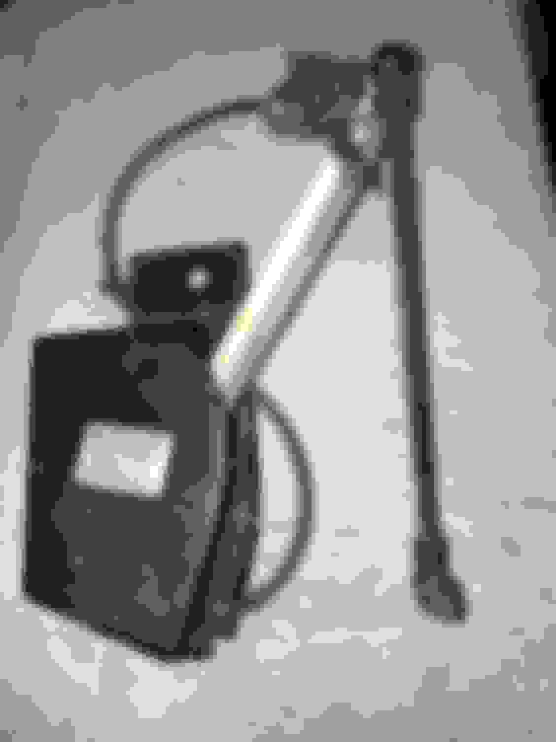
My 2001 Suburban 2500 LT with Auto Ride has electronic shocks and level sensors, no compressor. I had a friend scan my "Service Auto Ride" or "Service Ride Control" code and it came back with a RR sensor issue. This part number 22175469, the original bad level sensor, is no longer available. I swapped the left sensor to the right side and the right to the left. The trouble followed so I'm pretty sure it's the sensor. I bought a 2006 level sensor Dorman 926-799 since I had read somewhere that it can be used to replace the sensor that is no longer available. I received it but it has a different type of connection. The original had a pigtail with a connector and the new one has the connector built into the sensor with no pigtail. So I am trying to find a new connector so I can splice it into my existing harness or onto the old sensor pigtail. If anyone has a RR sensor part number 22175469 that is good then I be happy to buy it. In the mean time I'm trying to figure out where to find a connector. I went to my local wrecking yard and haven't been able to find a replacement old sensor or a newer vehicle I can snag the connector from. I'd like to just keep the Auto Ride and not upgrade to new shocks etc. Attached is the existing and the new sensor showing the connectors. Old sensor New sensor
Any help is appreciated.
Last edited by MrRenoman; Apr 23, 2019 at 8:58 PM.
Reason: Add part number
I did some research and I believe the connector for the new level sensor comes with several different part numbers for various applications...
PT1657
88953359
S1663
EC1160
This connector is used for:
Vapor canister purge
ABS modulator valve
Brake pressure sensor
Just to name a few.
They are quite expensive so maybe I'll try to hunt one down at the local wrecking yard.
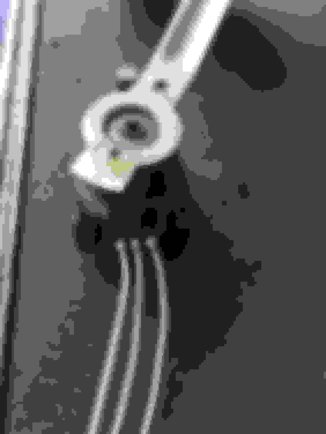
So I ended up ordering a PT1657 connector and it plugged right into the new level sensor. I cut the pigtail off the old level sensor and spliced the new connector to the old pigtail. This keeps everything plug and play and didn't require me to cut into the vehicle harness. Attached is a pic of the splice I did and the relationship of the old pigtail wire colors and the new plug pigtail wire positions. I went to the local library and used their online automotive manual. I deduced from the schematic how to wire it but it was hit and miss and luck to figure it out. Neither the new or old level sensor or connectors were labeled with the alpha characters (A,B,C) that the schematic detailed. The "Service Ride Control" light is off but I haven't confirmed if the system is working as designed. The sensor may be sending reversed information to whatever body module is processing the information. The "Service Ride Control" light is off and I'll see if I notice any ride difference. I used heat shrinkable crimp connectors then covered the entire pigtail with split convoluted tubing. Also attached is a pic of the completed and installed level sensor and harness. I did have to bend the arm of the level sensor so the axle moved the rod straight up and down instead of being pushed at an angle. The arm bent very easily to the desired positon.
Last edited by MrRenoman; Apr 24, 2019 at 2:56 PM.
Reason: add text
Update: Since I replaced the old level sensor I decided to see if I could dismantle it and determine what was wrong with it. What's interesting is the wires are molded directly onto the level sensor with a pig tail with a connector on the end as seen in the first photo in the initial post. So I took my air grinder with a small cutoff wheel and ground the plastic to see if I could expose the wire connectors. I was able to expose the stainless steel wire terminals and discovered that one of the wires to the sensor had an open in it. Although this worked, I would grind down closer to the wires to expose the wire to terminal connection. The area to grind away is very hard molded plastic. It looks like the wire connection unplugs from the sensor but it doesn't. After exposing the connectors I used the smallest drill I had and drilled holes in the exposed metal terminals. I then soldered wires to the terminals and tested the sensor. Per the schematic the center terminal looks like the signal source of some type of rheostat with the outer terminals being the outputs varying resistance depending on the position of the lever. Not knowing the resistance of the unit, I saw that the resistance was variable when measuring resistance across the center terminal to either outer terminal. I believe the problem with the sensor was an open wire and not the sensor itself. Grinding and exposing the metal terminals took some patience and the proper tool, a simple air grinder and a cutoff wheel. I used some liquid tape that I had to cover, insulate and protect the terminals and wires from the elements. I'm sure 2-part epoxy or some Right Stuff would work.
I may try re-installing to see if it works. It would be interesting since I am seeing variable resistance across the terminals. Attached are a few of pics. One pic show the part I cut off the sensor. The black wire broke off when disassembling. Another picture shows the exposed terminals that I drilled and soldered wires onto. And the last pic with the liquid tape.
Last edited by MrRenoman; Apr 24, 2019 at 3:44 PM.
Reason: Add text
Thank you for this brilliant post! I'm faced with the exact same situation and will try what you've done here. Did you ever try reinstalling the sensor that you fixed with the broken black wire?
Hope it's not too late to reach you. Regards,
Pete
Hi, I just logged onto this site. It's been awhile. To answer your question...I haven't tried the repaired part but am pretty confident it will work. Let me know if I can help. Thanks.
Originally Posted by psluszka
Thank you for this brilliant post! I'm faced with the exact same situation and will try what you've done here. Did you ever try reinstalling the sensor that you fixed with the broken black wire?
Hope it's not too late to reach you. Regards,
Pete