Three Battery Setup.
#11
CF Veteran
Join Date: Jul 2008
Location: Harrisonburg Virginia
Posts: 1,306
Likes: 0
Received 13 Likes
on
13 Posts
Once again, you missed the point. The relays serve to keep the batteries charged. The switch is ONLY when the A battery fails, and you need a jump. As for the degradation thing, you speak like someone who has endless money, or someone who hasn't experienced this.
#12
CF Pro Member
Thread Starter
So, how would you hook in the B and/or C batteries if A was unable to start the vehicle? Dig out jumper cables? That manual switch would be just for that scenario. As far as the separate relay thing, it's only a problem when charging isn't happening. When two batteries connected without any isolation, and one starts to degrade, it will draw down the other battery. Not an issue when charging, but why put the batteries through that? Less charge/discharge cycles means longer life.
I am thinking of one other idea, or I have been thinking of it. A Relay on each battery. I wouldn't do it because I am concerned about maintaining the health of the deep cycles, I would do this for functionality.
Thank you Stan for your input.
You explained very well why I was sitting here getting frustrated trying to explain that people having theories and people making decisions on real experiences... lead to two different results. Experiences like continually having dead batteries while you are going through hell. Not a good thing. I am rather sensitive to batteries now which is why I consider dedicating one exclusively to the Starter Motor and nothing else. If I do that, I will always have amperage to turn the Starter. Powering the rest of the required modules is another - seperate - issue. They do not require a lot of power.
Last edited by dberladyn; July 30th, 2019 at 12:44 PM.
#13
I understand the point perfectly, and as a matter of fact, I have first hand experience.
So you're driving your van around. Your switch is turned to ON because you need charge your aux battery(ies). You park the van and turn it off. Inevitably, one day, you forget to flip your switch back to OFF. You start to run your toys, and you run down your starting battery. It WILL happen.
By all means show us how you implemented your system, and let us know how well it works and how long it's been running. Tell us your degradation stories. I'm always open to learning something new.
You are all overthinking this.
#14
CF Veteran
Join Date: Jul 2008
Location: Harrisonburg Virginia
Posts: 1,306
Likes: 0
Received 13 Likes
on
13 Posts
Dan- another factor with batteries of this style is even the slightest corrosion on a terminal can cause an imbalance between batteries, and lead to failure. A relay for each battery isolates them from this.
Joe- You still don't get this. And part of this is because my skills lack the ability to draw out a schematic that I can post. But I'll try again. The switch would be off until the time comes when you need a jump. Isolator relays handle the charging. Both circuits exist together,and don't conflict.
Joe- You still don't get this. And part of this is because my skills lack the ability to draw out a schematic that I can post. But I'll try again. The switch would be off until the time comes when you need a jump. Isolator relays handle the charging. Both circuits exist together,and don't conflict.
#15
CF Pro Member
Thread Starter
Dan- another factor with batteries of this style is even the slightest corrosion on a terminal can cause an imbalance between batteries, and lead to failure. A relay for each battery isolates them from this.
Joe- You still don't get this. And part of this is because my skills lack the ability to draw out a schematic that I can post. But I'll try again. The switch would be off until the time comes when you need a jump. Isolator relays handle the charging. Both circuits exist together,and don't conflict.
Joe- You still don't get this. And part of this is because my skills lack the ability to draw out a schematic that I can post. But I'll try again. The switch would be off until the time comes when you need a jump. Isolator relays handle the charging. Both circuits exist together,and don't conflict.
If I do not decide to add a third relay I think I will just do this.
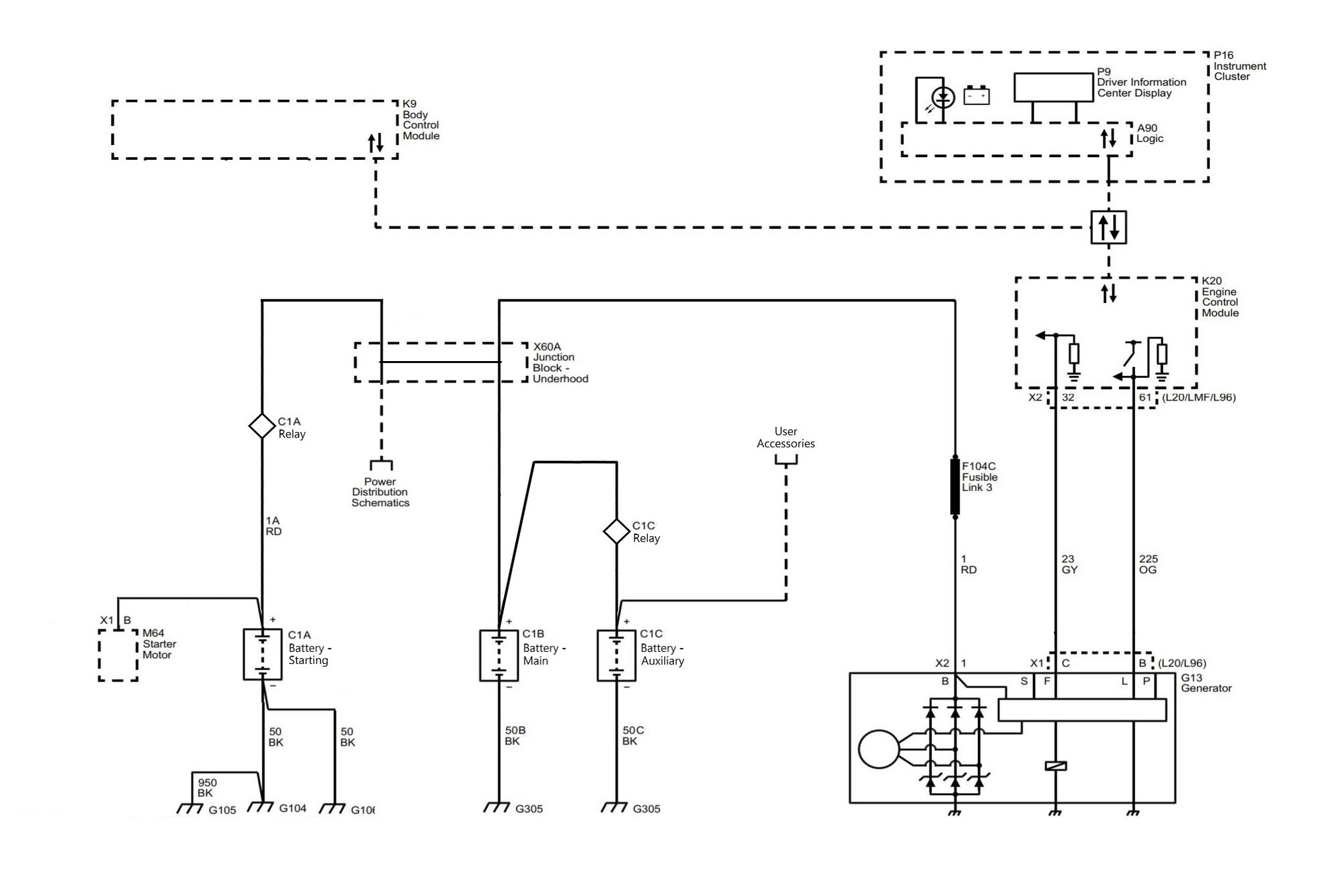
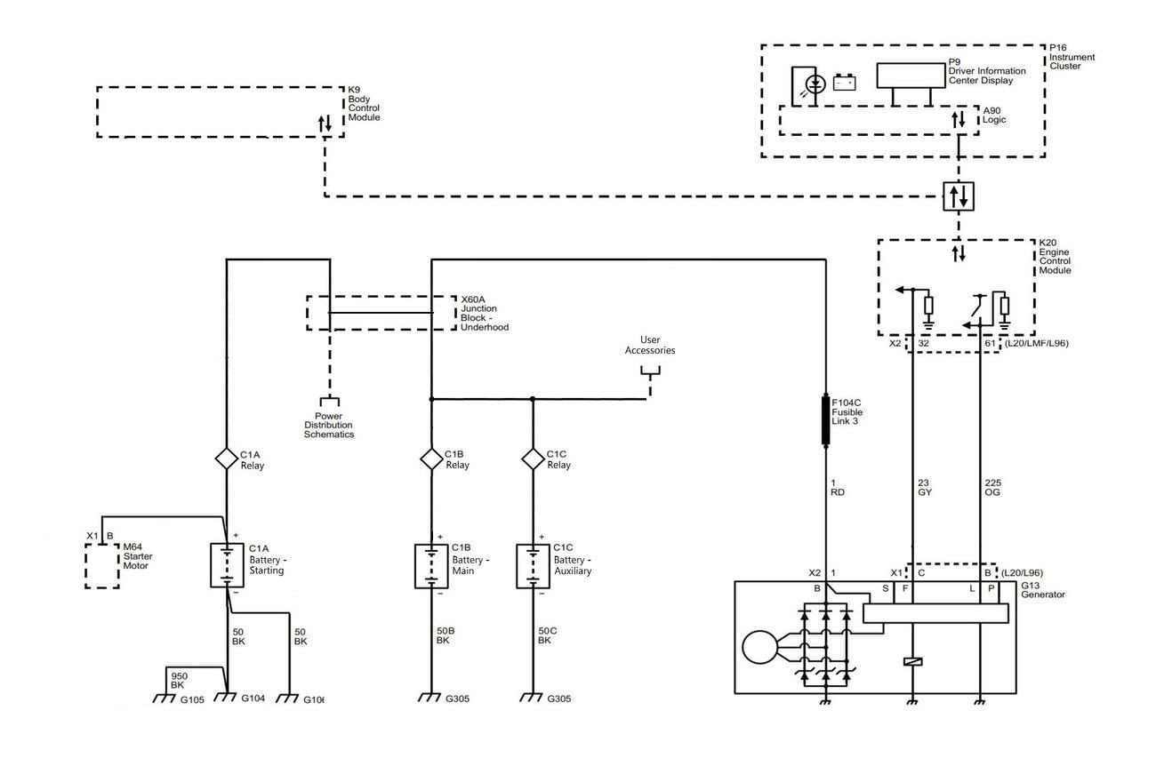
- C1A Relay will be triggered by the Alternator Charging. If that means I hook it into Ignition On, that is what I will do. For some reason that I forget right now, I was thinking of having it on a timer for something else. Maybe a delay before it kicks in and begins charging. A simple switch in the cab manually overriding the Relay Trigger takes care of a dead Main Battery.
- C1C Relay will be triggered by the Alternator Charging (as above). Again, a Manual Switch in the cab can be added to compensate for a dead battery somewhere else.
In this scenario a third relay would let me shut off the Main Battery if it was toast. Peace of mind thing I guess, that is all. What I lose is Engine Off operating time as I will be down to one battery for any function.

Last edited by dberladyn; July 30th, 2019 at 1:20 PM.
#16
CF Veteran
Join Date: Jul 2008
Location: Harrisonburg Virginia
Posts: 1,306
Likes: 0
Received 13 Likes
on
13 Posts
I don't think you need 3 relays, but I'd use relays for B and C. I'm not sure how a relay on A could work.
What do you use to make a schematic that you can post? My graphic skills suck.
What do you use to make a schematic that you can post? My graphic skills suck.
#17
#18
CF Pro Member
Thread Starter
I just edit the GM Upfitter docs with Microsoft Paint 3D. It actually works pretty good. I gave up the first few times, but persistence pays off. Now I am getting pretty quick at it.
This below is probably the luxury edition. It is probably also the best way to do it. A double throw, single pole manual switch in the cab for each battery would account for literally any situation. Each Relay could have a switch. Up for Pos+ 12 Volts (Manual Override), Center for 0+ Volts (Battery Disengaged), Down for Ignition 12+ (Automatic Battery Engage).
I do see a problem with this however. The Main (C1B) Battery Relay would constantly draw as it would always be engaged. I would need a Relay/Solenoid that was Normally Closed (ON), not Normally Open (OFF). Do they make those?
Maybe C1B would just have to be a 'Manual Switch' ?
Or maybe this feeds into what Stan is saying... with his Manual Switch example (kind of).

Last edited by dberladyn; July 30th, 2019 at 2:27 PM.
#19
CF Veteran
Join Date: Jul 2008
Location: Harrisonburg Virginia
Posts: 1,306
Likes: 0
Received 13 Likes
on
13 Posts
Think of it this way, Using the circuit that Dan posted with isolator relays separating all 3 batteries when the van is off. Add the switch, connecting "1" and "2" to B and C respectively, and connect A as the main. In the off position no batteries connect to anything. Switching it to "1" connects B and A (to jump A from B). Switching to "2" connects C in the same manner. Switch to "all" connects both B and C to A (the main battery) The relays handle charging when the van is running, and isolates the batteries at rest.
#20
CF Pro Member
Thread Starter
Think of it this way, Using the circuit that Dan posted with isolator relays separating all 3 batteries when the van is off. Add the switch, connecting "1" and "2" to B and C respectively, and connect A as the main. In the off position no batteries connect to anything. Switching it to "1" connects B and A (to jump A from B). Switching to "2" connects C in the same manner. Switch to "all" connects both B and C to A (the main battery) The relays handle charging when the van is running, and isolates the batteries at rest.
Maybe you are Right as above in Red.
Manual Switch - it is REQUIRED.
Last edited by dberladyn; July 30th, 2019 at 2:31 PM.


