When you click on links to various merchants on this site and make a purchase, this can result in this site earning a commission. Affiliate programs and affiliations include, but are not limited to, the eBay Partner Network.
General TechGood at troubleshooting? Have a non-specific issue? Discuss general tech topics here. IF YOUR QUESTION IS SPECIFIC TO A CERTAIN MODEL, IT DOES NOT GO IN THIS SECTION.
1994 chevy g20 - close loop runs rich - STOP CLEAN EVERY GROUND CONTACT FIRST!!!!
Hello,
I am having fun with my recently purchased 1994 chevy Van 5.7L troubleshooting a rough idle and rich mixture problem. I have researched several blogs and youtube videos around these symptoms. And I have replaced several parts to address potentials issues.
I am restoring this van. So I do not mind adding new parts to build a baseline of what is a known good for future maintenance and repairs.
I am trying to avoid blind R&R parts changing. So I broke out the voltmeter, wiring diagram and owner manual. There are no engine codes other than self-induced by unplugging sensors for troubleshooting.
I am working around a Blackbox situation. The van is OBD1 so I am not able to read live ECM data to determine if fuel trim or other conditions exist. I have tried to use an OBD1 to ODB2 adapter for my scanner without any luck.
My observations:
The van runs fine with the Coolant Temperature Sensor CTS disconnected from a cold start. I believe this is an open-loop mode. So the ECM is of less priority for engine performance.
The yellow CTS 5 volt reference circuit is reading low voltage at 1.98 volts consistently and at the ECM connector back probed reading.
I believe this is the main culprit a low reference voltage for engine temperature. So the ECM is out of the picture.
The van runs on the cooler side 170f even with a 190f thermostat and the front grill covered with a blanket.
New Parts list [known good]:
Tune-up: new spark plugs, plug wires, distributor, cap, rotor, PVC value, EGR value, set timing,
New CTS
New thermostat
Reconditioned ECM
Reconditioned Fuel Injectors
I have fabricated a buzzer rig to be connected to the CTS yellow 5v reference wire so I can inspect and wiggle the harness and hopefully locate any wiring shorts or issues.
The buzzer sound change in tone should tell me there is an issue in the yellow 5v circuit at that point in the harness. I have found No buzzer sound change yet. :-(
Any ideas, suggestions, and/or directions are much appreciated. I have waited many years to own a Chevy van once again. :-) I rather not drive her in open-loop mode.
Thank you for your time.
Mike.
Last edited by IRON MIKIE; Dec 8, 2019 at 10:24 AM.
Mike, If the truck is staying in open loop one of the possibilities would be the Oxygen sensor itself. There aren't many scan tools around anymore that will show live data for these systems anymore but if you could find one the voltage reading would probably show "fixed". A normal sensor would fluctuate but if the sensor is failed it would provide a constant reading. It's not an expensive guess if you want to try it. This would be the sensor(s) closest to the engine.
Best of luck, John
I replaced the O2 sensor the idle issue still exists. Time to open the classic black box and get ECM live data. I believe this tool will read OBD1 live data.
CP9690
Elite AutoScanner Kit Enhanced OBD I and OBD II Scan Tool
The Diagnostic Software
The last item needed is the diagnostic software that will run on your laptop to collect and record the data from your OBD1 system. There are a number of excellent software packages available, with some of them being free and others giving you a trial period of fully functional use. Screen shots and links to each website are provided below for each of the software packages I have found and loaded up for myself. I'm not endorsing one scanning package over another, as they all have their place and will provide critical data. I can say I've used Tunerpro RT the most, and it is an excellent package in the way it's laid out and the data it provides. I've also used TTS Datamaster, and it is also an excellent package in the way it's laid out and the data it provides. You can use it 20 times on data recording runs before purchasing a key, and you can view previously recorded data any number of times while on trial, before purchasing a key. For the 160 baud cars, WinALDL seems to be the most widely used package and Jonas Bylund has done a great job with it.
Below are some screen shots of some of the software packages. There are many more screens to all of these packages, I've just included a few for viewing here. You can click on the image to get a larger view, and the title link below the picture will take you to the packages website.
I took the van for a one-hour test drive to give the ECM time to learn. The van ran very well on acceleration, good on idle after high-speed driving, and good on mid-range driving. I parked the van at home and shut off the motor.
20 minutes later going for a 2nd test drive, I started the van and the motor idle was very rough. I placed the van in reverse and the motor shut off. The motor would not start from that point of failure. The condition behavior seems to be the timing was advanced to far.
The faster the starter turned the motor would fire but not run. So off to the beach to go fishing. :-)
6 hours later, from a cold start the 1st attempt was not successful. I had to crank the motor far too long and depress the gas pedal to get the motor to start. After the warm-up the motor would idle ok. I did not go for another test drive it was dark outside.
Day 2 now. I think I will wait on the ALDAL software and cable to get live ECM telemetry data. Chasing ghosts NOW!
I need the GhostBusters on this one.
Thanks,
Mike
Last edited by IRON MIKIE; Dec 8, 2019 at 6:59 AM.
Here is a good read on the ECM logic and parameters.
The 94 Plus EEPROM is even larger. The factory ECM/PCM has a Learning capability that allows it to make corrections for minor variations in the fuel system to improve performance and driveability.
There are two learning features. The Integrator and Block Learn (I and BL) and Block Learn Memory (BLM) cell. The I and BL feature is normal with a value of around 128.
If this value is higher than 128, it indicates that the ECM is adding fuel to the base fuel calculation because the system is running lean, a value lower than 128 indicates that the ECM is taking out fuel because the system is running rich.
The integrator is a short term corrective action while the BLM is long term correction. The BLM value will change if the integrator has seen a condition that lasts for a longer period of time.
There are from two to sixteen different cells which the ECM modifies, depending on RPM, airflow or manifold air pressure and other conditions such as AC "ON" or "OFF", etc.
The ECM learns how much adjustment is required in each cell, retains it in memory, and applies these adjustments when the engine operates in that cell or RPM - Load Range.
These features of the OEM ECM allows the system to adjust itself AUTOMATICALLY to your engine and assure peak performance for stock and other than stock engines.
When the vehicle power is disconnected for repair or to clear diagnostic codes, the learning process has to begin all over again.
To TEACH the ECM, drive the vehicle at operating temperature with moderate acceleration and idle conditions.
Performance Calibrations typically change the parameters for fuel flow, fuel cut-off and spark advance-timing and will allow increased fuel flow and modify the spark advance curves during rapid acceleration.
WHAT THE ECM - PCM DOES: The TPI system utilizes the following sensors and devices to control the engine:
Mass Air Flow Sensor, Manifold Air Temperature, Coolant Temperature, Oxygen Sensor, Throttle Position Sensor, Cold Start Switch, Cold Start Injector Fuel Injectors, Idle Air Control Valve, Distributor Electric Spark Timing, (Module in the distributor)
Electric Spark Control, Module and Knock Sensor.
When the starter is engaged and the coolant temperature is less than 100 deg F. The cold start injector provides a spray of fuel, of 8 seconds duration max, to each cylinder via an air distribution system built into the intake manifold.
If the engine temperature is greater than 100 deg F, the cold start injector is disabled by the cold start switch. Upon startup, the ECM utilizes information in the calibrator to establish the initial pulse rate for the injectors and the engine starts. At this time the engine is operating in open loop mode and will continue to do so until the engine warms up. After the warm-up period, the ECM scans the sensors if all sensors are operating and within their proper range, the engine then goes into closed-loop operation.
This means that the sensors are dynamically controlling the engine. In the event the information received is higher or lower than the normal range, a code will set in the ECM, and the Check Engine or Service Engine Soon light will come "on".
The ECM receives information on airflow, engine temperature, air temperature, exhaust gas oxygen content and throttle position. This information is used to calculate the proper pulse width for the injectors and fires the injectors for the calculated period. This procedure is repeated continuously in very rapid sequence to maintain the optimum fuel-air ratio.
The electronic spark control components provide maximum advance if engine knock is detected the spark is automatically retarded. This too is a continuous process.
It should be noted that the following components are MATCHED for optimum performance; Distributor - EST module, ESC module, knock sensor and ECM calibrator.
These components are not interchangeable between 5.0L - 5.7L engines. 5.7L components referenced are recommended for 327 - 400 CID engines. 5.0L components are recommended for 265- 305 CID engines.
Last edited by IRON MIKIE; Nov 19, 2019 at 7:39 AM.
The CTS yellow wire 1.89 volts should be 5 volts. The CTS black [ground] read .018 volts. If I unplug the IAC at the TBI unit the voltage goes to .024 volts on the CTS black wire.
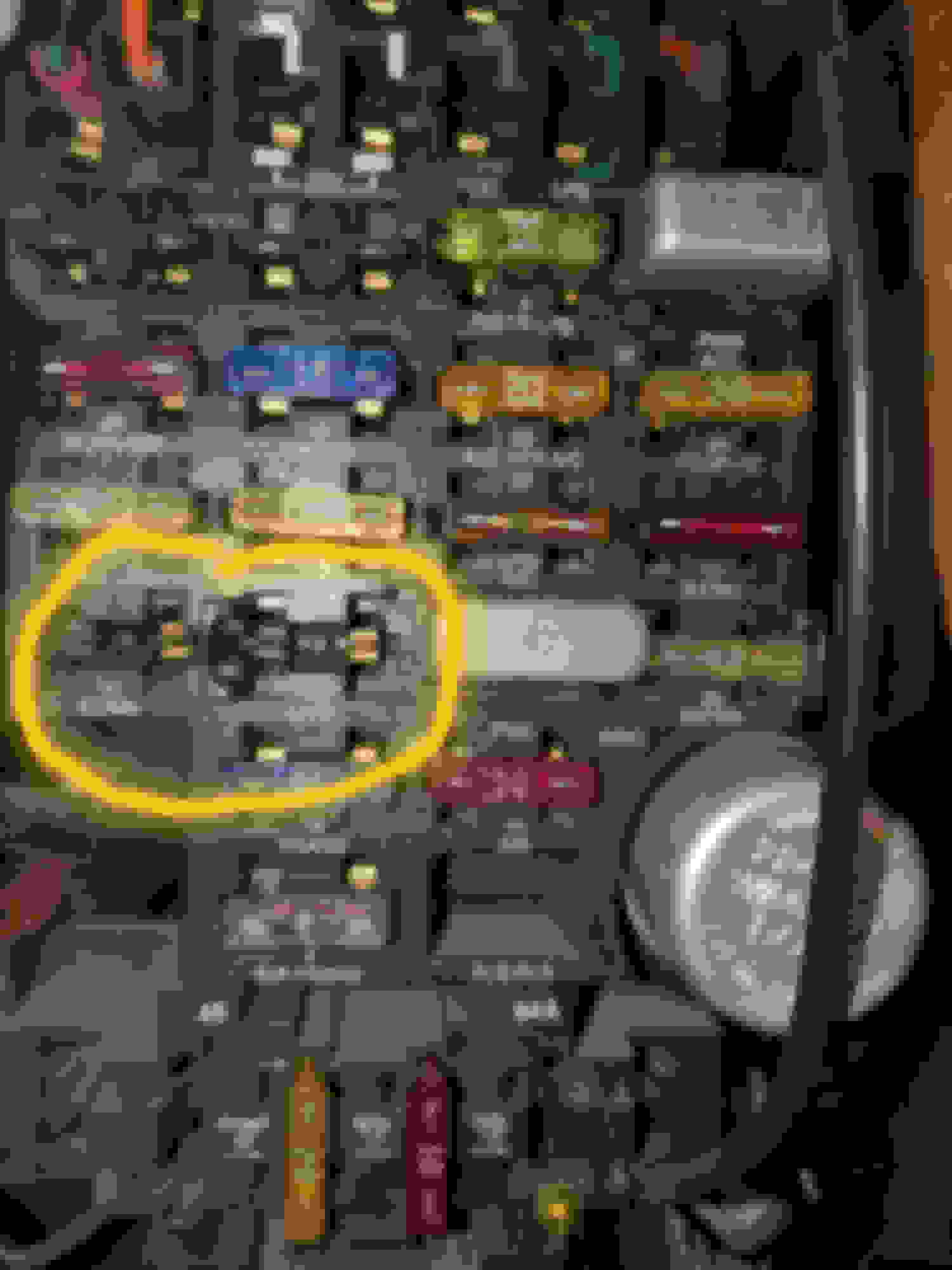
At the fuse box -
ECMB fuse unplugged - left .01 volts -- right side 12.47 volts
ECMI fuse unplugged - left .00 volts -- right side 12.47 volts
I notice the left ECM terminals are dis-colored they are not copper/brass color like the other fuses.
How hard is it to remove the fuse box on a 1994 chevy van g20? I will have to remove the driver's seat to get under the dash.
Last edited by IRON MIKIE; Nov 19, 2019 at 5:04 PM.