When you click on links to various merchants on this site and make a purchase, this can result in this site earning a commission. Affiliate programs and affiliations include, but are not limited to, the eBay Partner Network.
Where to tap into dome light circuit for power for foot well lights
Tahoe & SuburbanThe power, space, and brutal towing ability make the Tahoe and its longer sibling, the Suburban, arguably the best full size SUV's on the market today.
Where to tap into dome light circuit for power for foot well lights
I have a 2007 Tahoe LT that I wish to have foot
well lights in. I have read every forum thread on the internet that I can find about where to tie into the dome light circuit, and so far, all of the listed modules, and connectors and wires are wrong.
NONE of them go out when the dome lights go out, some don't have power to begin with, and at least one of the connectors doesn't even exist. At least two of the connectors when unplugged kill the dome lights, not just one, and the gray wires are NOT the ones, because when the dome lights go out, the test light stays on. The gray wires in the "A" pillar are also not the ones.
There is no danger in overloading the circuit by adding the lights, as I have just replaced all dome bulbs with canbus LED's operating at much less wattage. There. That should address all the wrong answers before they occur.
Does anyone have a different solution that works, short of just going to one of the dome fixtures and tapping into the hot lead there? As far as I can see, that is the only solution to getting foot well lights that will come on with, and go off with, the dome lights. (and I still have to figure out which wires in the fixture are the dome and not the map light).
I'm doing the same on my Savana, because my old van had them and it looks like GM is trying to shave off a few bucks wherever they can nowadays. Luckily the dome circuit is available in the driver and passenger side harness. I don't know about your truck specifically, but I used the upfitter manuals and I'm sure they'll work for you.
Thanks, however I visited the site and even with my limited intelligence, I don't even understand the site or how it works.
Originally Posted by mountainmanjoe
I'm doing the same on my Savana, because my old van had them and it looks like GM is trying to shave off a few bucks wherever they can nowadays. Luckily the dome circuit is available in the driver and passenger side harness. I don't know about your truck specifically, but I used the upfitter manuals and I'm sure they'll work for you.
I have a 2007 Tahoe LT that I wish to have foot
well lights in. ....and the gray wires are NOT the ones, ...and I still have to figure out which wires in the fixture are the dome and not the map light).
Thanks in advance for any help.
On Page 236-237 (GMUpfitters) it looks like you need to find the GRAY wire on the MBEC(left I/P fuse block):EDIT-This is the left I/P Junction block not the fuse block. Didn't understand what MBEC was referring to.
connector P260-terminal B4, or
connector P407-terminal 4, or
connector P259-terminal 5 On pages 35-36 they show the connectors on the fuse block, but the labels don't match the schematic labels .
Don't shoot the messenger, I'm just telling you what the schematics are telling me. It's a matter of finding the correct GRAY wire.
If you look at the lights, the ORANGE wire will be going to the switch for the Reading lamps, and the GRAY wire for power to the Dome lamp.
Hope this helps you, Good luck
Last edited by a55bruce; Apr 23, 2019 at 9:40 PM.
Reason: Fixing my errors
Oh, I'm not shooting the messenger! I really appreciate your help. I'm just not capable of reading electrical schematics I found this .gif image of the IP connector block which is the one in the photo I posted earlier. Like you said, the labels on the diagram I found don't match the label numbers assigned in the schematic. All of this I believe to keep people like you and I from figuring out how to work on these beasts. They have purposely complicated everything beyond belief, to force you into their shop to have them worked on. What I did, was take my 12v automotive tester, ground the ground lead, then made a test probe that would fit into the little boxes in the connectors and stay there, contacting the pins. I found the connectors that would kill the dome lights when pulled (the Gray and Green connectors) plugged them back in and tested the gray wires and ALL wires on those connectors. The test light would remain lit even when the dome lights dimmed and went off, or on some pins, it never lit the test light, on others, it dimly lit the test light but wouldn't go out with the dome lights. I also tested the gray wires on all the other connectors, as well as two I found in the driver side A pillar.
Find the diagram that has the dome/courtesy lights.
In this example from my vehicle, the dome/courtesy light is:
- Circuit # 149
- wire color dark blue w/white stripe
- Connected on pin H8 in the X2 connector on fuse block (where they are labeled)
- goes through harness connecter X420, Pin B
That should be enough to get you started. It may seem complicated, but there are miles of wire and the schematics were designed to consistently pinpoint and work on electrical components. The vehicle is divided into 'zones'. All numbers in the 100's are in one place, 200's in another etc.
The harness is usually split into sections. The instrument panel section, door section, ceiling section etc. and they connect to each other with big plugs. If you search the document for the circuit number "149" it will show you all the involved pieces, and how to find it in each connector, the color, the wire gauge etc. The manual even has drawings of where each of these connectors is located. It's an invaluable resource. If you want to do your own wiring, it's worth learning some electrical problem solving.
Last edited by mountainmanjoe; Apr 23, 2019 at 1:16 PM.
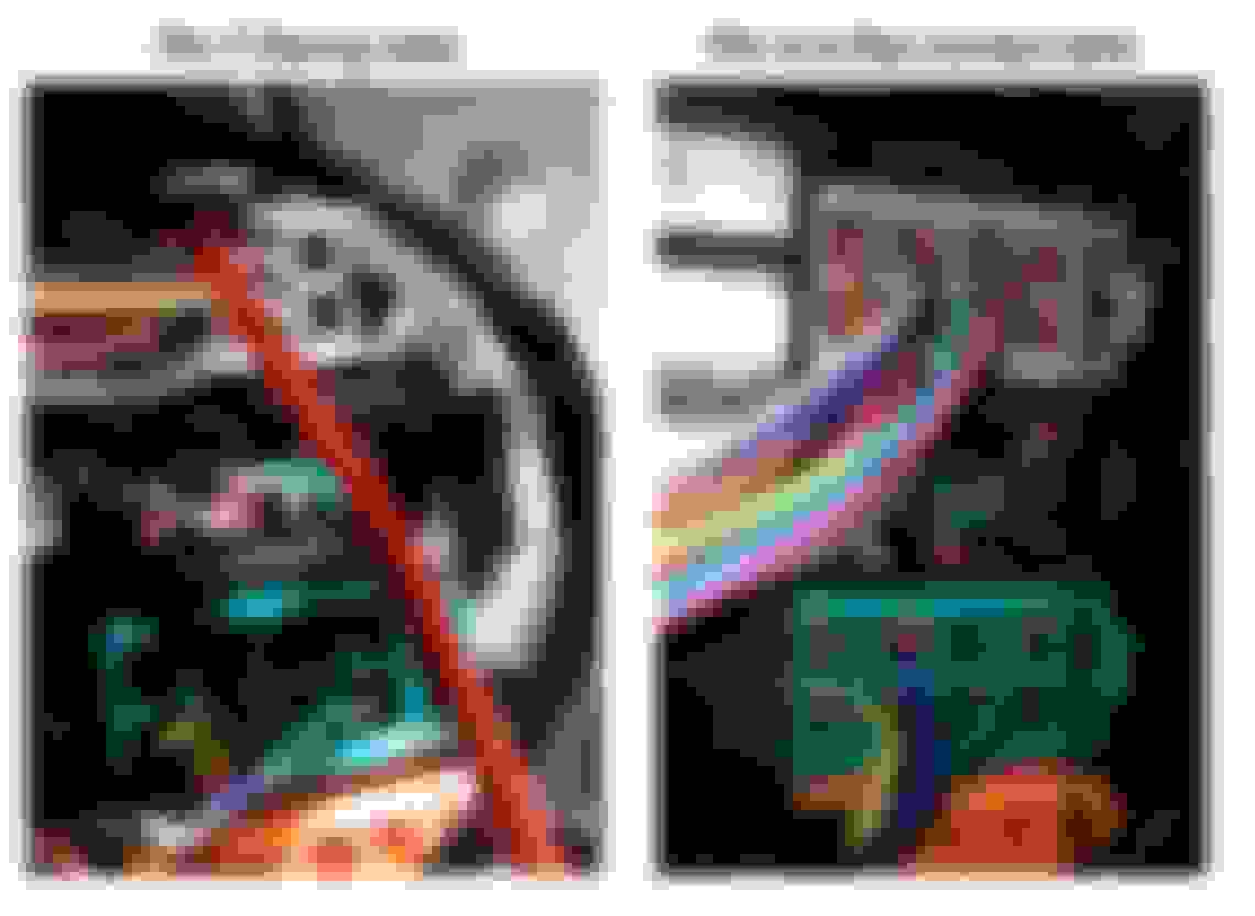
The photo I was referring to was in my original post, but has since vanished for reasons unknown. But here it is again this time focused on the top right connector (the GRAY one. I had tested ALL the sockets on it before with the tester, but for some reason did not get a hit on pin 4 (buried behind the red tester lead in the first photo) and this time I hit it and it lit, so I closed the door and waited, and sure enough the tester lamp dimmed with the domes and went out when they did. pulled the other wires out of the way and found a second gray wire in pin 4. PROBLEM SOLVED.
Originally Posted by a55bruce
I'm not seeing the photo you're referring to.
After starring at the .gif image for a few minutes, puzzling why it didn't look like the diagram in the GMUpfitters document....
I realized we're talking about 2 DIFFERENT parts.
Your image is not the I/P FUSE BLOCK that I'm referring to.
Check page 37(B-17) in the GMupfitters, you're checking item-4, I'm referring to Item-7.
Hopefully this will get you to the correct wire.
If not, go to the dome light and do the test probe at the lamp itself (sanity check of the test probe, and schematic interpretation).
Thanks. Finally found it this morning, see my last post in the thread with the images of the second gray wire I found in the top right connector. Thanks again for all your help!
Last edited by Disasterman; Apr 23, 2019 at 3:22 PM.


 Didn't understand what MBEC was referring to.
 .
. I'm just telling you what the schematics are telling me. It's a matter of finding the correct GRAY wire.