When you click on links to various merchants on this site and make a purchase, this can result in this site earning a commission. Affiliate programs and affiliations include, but are not limited to, the eBay Partner Network.
Tracker1989-2004
This compact SUV proved itself to be a fine ecnomical vehicle, good for making its way along any type of surface. Platform: CAMI (Suzuki)
I need to replace the ECT sensor on my 2.5 L v6 2002 tracker but know little about working on cars. A mechanic told me that depending on the location, the replacement could take 1-4 hours. For a $40 part I don't want to pay for 4 hours of service. Does anyone know how long this job takes or how easy it would be to do myself?
The service manual implies this is a ten minute job. Be prepared to spend an hour or more.
Halfway down the transmission dipstick tube you will see the ECT sensor screwed into the back of the engine.
Your first challenge is to remove the electrical connector. You must press the release tab and simultaneously pull
the connector to the rear of the car. This is not easy and may require several attempts. The next step is to turn the
22 mm nut counter-clockwise until the sensor comes out of the engine. You may find it helpful to first remove the
12 mm bolt holding the dipstick tube to the engine. This will give you just enough clearance to get a wrench on
the sensor in a way that you will be able to turn the wrench. If you did not drain the radiator, fluid will spew out.
It's safer if the engine is cold when this happens. This is a totally doable job for a beginner. It's just going to take
longer and be more frustrating than you expect.
Unlike newer cars with sensor data multiplexed onto class 2 serial busses or Controller Area Networks (CAN), the Tracker uses good old fashioned dedicated wire
analog gauges. It's more expensive to run a separate wire for every circuit but it makes it easier for the DIYer to troubleshoot. In the case of the coolant temperature
sensor the Tracker uses a dual-element sending unit. One output is sent directly to the instrument panel and the other is sent to the computer.
Any scanner that can read real-time data will show the value being sent to the PCM.
The instrument panel gauge should indicate a similar value. The coolant temperature can be
verified with an infrared thermometer at the thermostat housing.
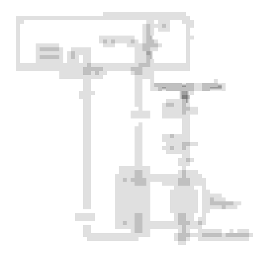
The Tracker ECT schematic (above) has a small error.
When Chevy redrew the Suzuki schematic to conform to GM specifications they
inadvertently tied both ECT elements to sensor ground. This is incorrect. Only the
element going to to the PCM uses the sensor ground. The element going to the
instrument cluster uses a chassis ground (where it threads into the engine block).
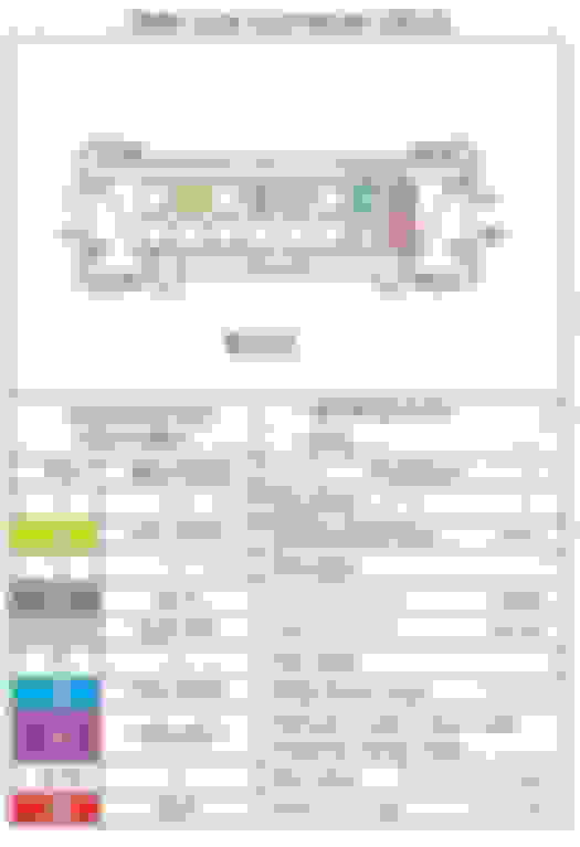
Chassis ground is pin 4 on the Data Link Connector (DLC) while the sensor
ground (aka signal ground) is found on pin 5.
Except for G102 & G103 all the grounds on a 2001 V6 are chassis grounds.
The three round lugs that comprise the sensor (or signal) grounds terminate at a signal point on
the rear of the intake manifold (driver's side).
This morning, as I was checking the ECT sensor harness, I found that the sensor was loose. Not loose where the sensor screws into the head. Loose internally. The connector portion of the sensor wasn't screwed tight in its housing. I turned the sensor connector clockwise and it tightened right up.
I thought this was odd. So I grabbed two spare ECT sensors I had on hand, and gave them a twist. Both were solid and tight; neither was spinning internally.
I have no doubt this could be the source of the P0117, but I thought I'd bounce it off you. What I intend to do is drive it today and see if tightening the connector solved the problem.
(I replaced the thermostat last year because the engine never seems to reach full operating temperature, according to the temperature gauge. The new thermostat didn't fix the problem. However your writeup above, in particular the part about the same ECT sensor driving both the PCM and the temp gauge, got me thinking today that this sensor might be the cause of both problems.)
Thoughts appreciated. Thanks again.
Last edited by rallison203; Aug 13, 2024 at 9:30 AM.
>> the engine never seems to reach full operating temperature, according to the temperature gauge.
On page 6-1397 of the purple 2001 Tracker FSM you will find the "Temperature vs Resistance" chart for the ECT sensor.
You can test the sensor's calibration with an ohmmeter, thermometer and some hot water.
Thanks L84sky. I did the next best thing. I swapped out the sensor and took it for a test drive.
Everything works fine now including the heat to the heater box. That one has me stumped but as they taught us in school, "don't argue past winning." So I sewed it up and it's ready to go.


 '02 tracker ECT sensor