When you click on links to various merchants on this site and make a purchase, this can result in this site earning a commission. Affiliate programs and affiliations include, but are not limited to, the eBay Partner Network.
Tracker1989-2004
This compact SUV proved itself to be a fine ecnomical vehicle, good for making its way along any type of surface. Platform: CAMI (Suzuki)
The 2001 Tracker had three engine options: G16, J20 and the H25
All three engines use a different Camshaft Position (CMP) sensor.
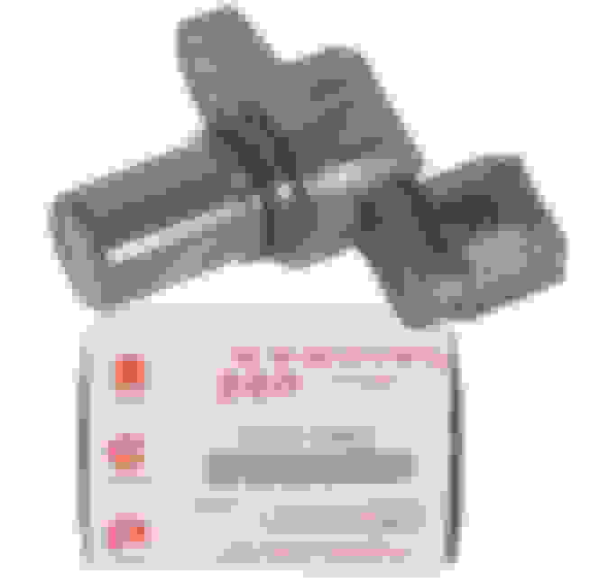
This is the CMP sensor for the 1600 cc G16 engine.
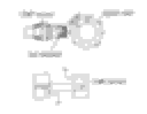
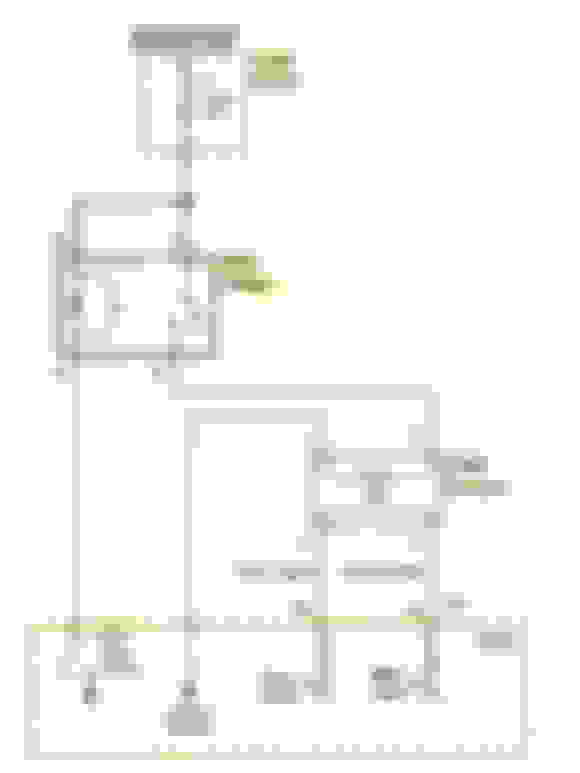
Inside the G16 CMP sensor a semiconductor device called a Hall-effect switch is placed next to a permanent magnet. When the metal tabs on the reluctor wheel rotate past the the magnet, the Hall-effect switch detects the disruption in the magnetic field. That disruption is converted to a digital signal which can be read by the PCM. The reluctor wheel itself is not magnetized.
The spacing of the tabs on the reluctor wheel produce a unique pulse width for each cylinder. By measuring that pulse width the PCM knows when each of the four pistons is approaching Top Dead Center (TDC). After looking at ECT, MAF, IAT and RPM data; the PCM calculates the optimum time to fire the spark plug for each cylinder. Note that the unique pulse width pattern produced by the CMP sensor is spread over two rotations (720�) of the crankshaft. That is because in all 4-stroke engines the camshaft turns once for every two revolutions of the crank. Each piston reaches TDC twice in the 4-stroke process. The CMP sensor ensures that ignition spark only occurs on the compression stroke. The distributor used to perform this function on older cars until Coil-On-Plug (COP) technology made the distributor obsolete.
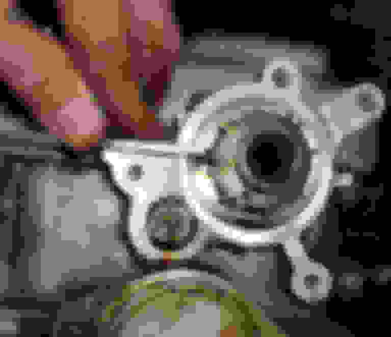
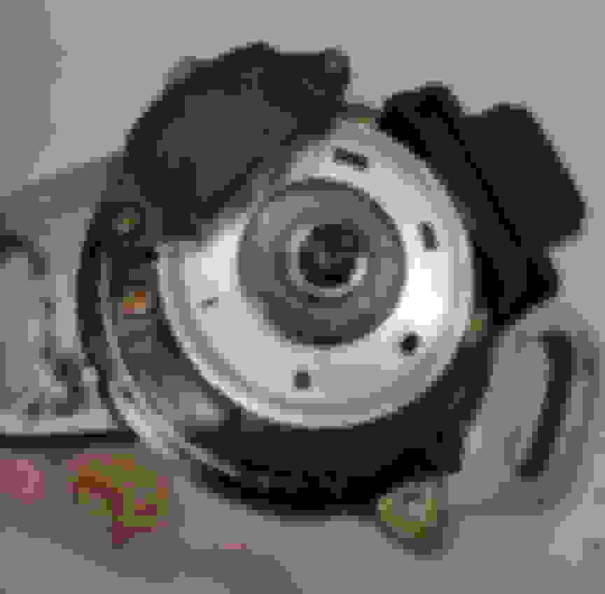
This is the reluctor wheel for the G16 CMP sensor.
It attaches to the end of the camshaft.
It is covered by what Suzuki calls the "distributor case."
The G16 CMP sensor bolts into the reluctor wheel cover.
The reluctor wheel must be positioned on the cam with precision because the G16 CMP sensor is not adjustable.
The 2000 cc J20 engine CMP sensor assemby contains both the Hall-effect switch and the reluctor wheel.
Unlilke the G16 CMP sensor, the J20 sensor is adjustable. Other than that, the two sensors work the same.
Both Hall-effect sensors are 3-wire devices: power, ground and signal.
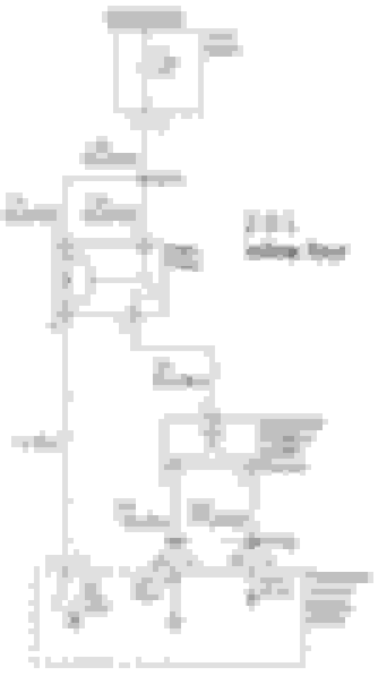
The CMP sensor for the H25 engine is not a Hall-effect sensor.
It is instead a 4-wire optical sensor using an infrared (IR) transmitter and receiver. The IR beam is broken by a rotating interupter disk.
The H25 sensor provides two signals to the PCM. One is the position waveform like that produced in the Hall-effect CMP sensors above, and the other signal is a series of uniform reference pulses.
The position waveform is produced by the different sized windows in the interrupter disk.
The sequence of the POS pulses determines the firing order in both types of sensors.
Last edited by L84sky; July 21st, 2021 at 6:46 AM.
 July 15th, 2021, 9:53 AM