Tracker 101: intro to grounds
#1
CF Senior Member
Thread Starter

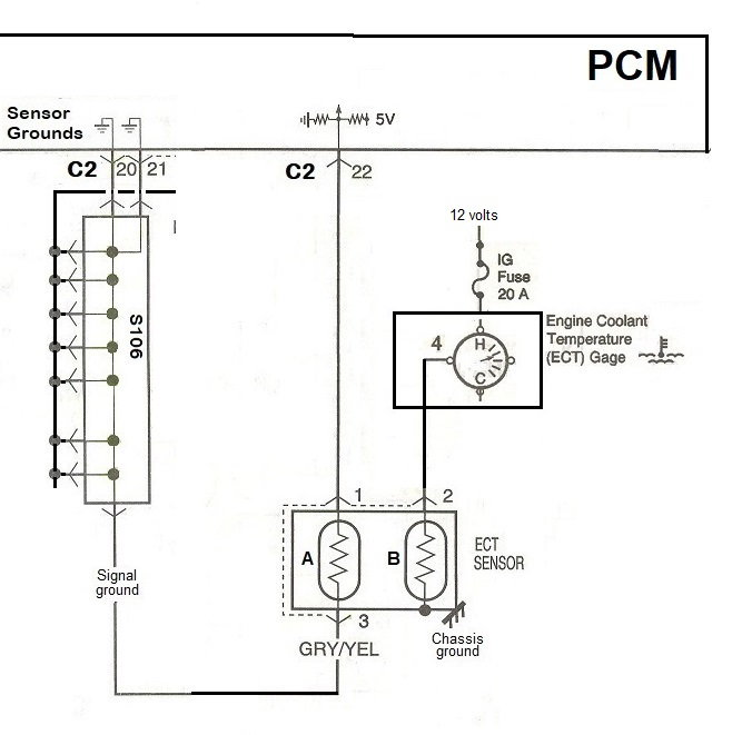
The Tracker has two types of grounds. Pin 4 on the Data Link Connector (DLC) is connected to the chassis ground and pin 5 is the signal ground.

The difference between the two is demonstrated by the V6 Engine Coolant Temperature
(ECT) sensor. The ECT has "A" and "B" thermistors inside the sensor. The thermistor's
internal resistance changes with temperature. Thermistor "B" operates on 12 volts and
uses the chassis ground (the steel frame of the car). Thermistor "A" operates on 5 volts
and uses the sensor ground which originates inside the PCM.

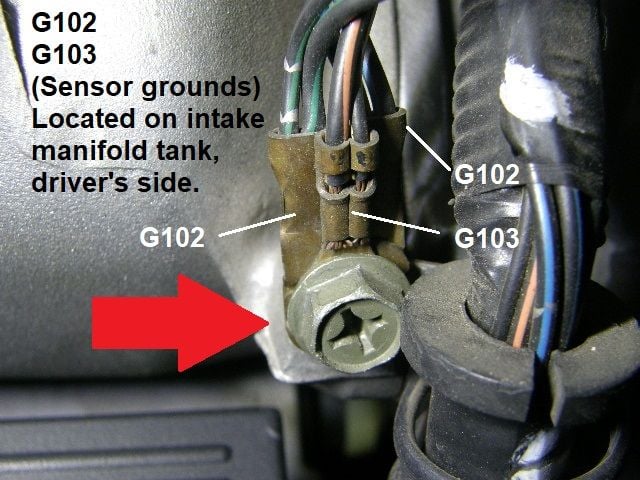
Suzuki says there are twelve grounds on the 2001 Tracker, Chevy says there are eleven, I say there are ten.

The discrepancy comes down to how many sensor grounds you think you have here.

Suzuki says there are three grounds here (3,4 & 5). Chevy says there are two (G102 & G103). I say the screw head
is the ground and there is only one. The sensor grounds use this single-point or star bonding technique to avoid
ground loops. Ground loops occur when different ground locations have a slight voltage difference between them.
Grounds loop are not usually a problem until measurement precision is required. In the case of ECT sensor, the
IP temperature gauge signal just needs to be a ballpark figure. On the other hand, the ECT signal to the PCM is
used to determine engine performance.

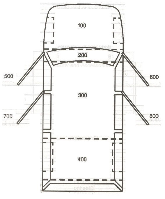
Chevy labels the grounds by zone. All engine bay grounds start with G1xx.


Last edited by L84sky; November 11th, 2021 at 1:53 PM.
#2
CF Senior Member
Thread Starter

Grounds G200 and G201 are connected to the chassis with "splice packs."

The splice packs can be removed for troubleshooting.

The splice pack has an internal "comb" that is bolted to the frame.

The comb can be replaced with a set of jumper wires for troubleshooting.

I assigned arbitrary designations to each ground wire. Then I unplugged each jumper one at a
time to find out which circuits it controlled.

I was able to draw a map of the splice packs.
Download full-size drawing here: https://www.dropbox.com/s/gcqyn7bgsu...%2016.jpg?dl=0

SP200 and SP201 share the ground on pin "E." Unplugging the jumper from pin "E" of just one of the splice
packs has no effect on the pin "E" circuits. Both splice packs have to be removed to eliminate the "E" ground.

This is a map of all the 2001 Tracker LT grounds.
Download full-size drawing here: https://www.dropbox.com/s/xuniczo98p...%2018.jpg?dl=0
Last edited by L84sky; December 28th, 2020 at 3:59 AM.
Thread
Thread Starter
Forum
Replies
Last Post


