

Remote Starter Range


CF Junior Member
Joined: Nov 2006
Posts: 52
Likes: 0
From:
Has anyone found the info from a prior post below to be correct?? Before I go looking for this wire...I want to know if the range increased and by how much. Thanks
"By pulling the wire (looks to be 18 gauge with a clear sheath and black electrical tape covering the tip) out of the mass of other electrical wires, and sticking the end (plus 2" or so) of the wire outside the trim along the bottom of the window, the range is increased."
"By pulling the wire (looks to be 18 gauge with a clear sheath and black electrical tape covering the tip) out of the mass of other electrical wires, and sticking the end (plus 2" or so) of the wire outside the trim along the bottom of the window, the range is increased."

Thread Starter
CF Senior Member
Joined: Oct 2006
Posts: 321
Likes: 1
From:
I can verify that the range has increased. It is double what it was with the wire inside the bundle. I ordered that antenna from Crutchfield (posted yesterday) and will install and test it as well.
You really have nothing to lose by pulling the wire out. It's really a 10 minute job. If it doesn't work to your satisfaction, just put it back and be done with it. BUT.... if it does work, just send ZX lots of money for telling us where the wire is. ;-)
You really have nothing to lose by pulling the wire out. It's really a 10 minute job. If it doesn't work to your satisfaction, just put it back and be done with it. BUT.... if it does work, just send ZX lots of money for telling us where the wire is. ;-)
Thread Starter
CF Senior Member
Joined: Oct 2006
Posts: 321
Likes: 1
From:
Just pop the oval out with a small flathead screwdrver - there's a screw under it.
There are some retaining clips that hold it on but you should have no other problems.
There are some retaining clips that hold it on but you should have no other problems.
Thread Starter
CF Senior Member
Joined: Oct 2006
Posts: 321
Likes: 1
From:
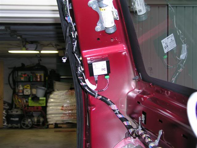
OK... Thanks to Mr. ZX, there was no major hunt for this little device. It was exactly where he said - D pillar about half way up on the driver's side.
It took me about 5 minutes to figure out the best way to remove the interior of the Tahoe. Once I figured it out, it took 5 minutes to pull it all out. By all, I am referring to the upper trim on the D pillar, the bottom threshold plastic at the tail of the truck, and the massive side panel that hides the jack (I didn't even know it was there - sad I know).
There is a small black box labeled Omron. That's the toy to play with.
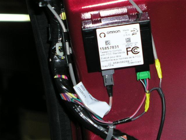
Anyway.... there are two connectors on it: one has a 12" clear insulated wire (the antenna) and the other is a green molex connector with 3 wires. The ground is the black with white stripe (I took an Ohm meter to confirm that it grounded).
Per the instructions, I stripped off a small bit of the insulation from the ground wire and soldered the first of two wires to it. I then stripped 1/4" of the insulation from the far end of the antenna wire and soldered the other wire to it. I wrapped electrical tape (yellow so I know it's my work) around the new connections and secured the wires.
Just to be on the safe side, I re-connected the Omron box and tested all of the remote's functions. All is still working.
Then I ran the 10' wire to the forward end of the cargo window and stuck the antenna to it vertically according to the instructions. As I moved away from it, wouldn't you know it?? The thing fell off the window. Obviously the adhesive they use is a bit crappy. I taped it in place until later.
My next step was to actually test the distance. I walked up my street a good 6 houses (not sure of the distance but the average frontage in my development is about 115 feet) which is about 800 feet give or take. I sounded the horn alarm, locked and honked, then started it. So far so good.
It was all great up to this point. Putting it all back together. That took about 20 minutes or so to do.
As for the antenna and poor sticky stuff... I had some glue-backed velcro in the garage which did the trick.
I did take pictures of everything but have to go for some Physical Therapy on my shoulder (had rotator cuff surgery 19 days ago). And yes, I was able to do this install with one hand!!! When I get back later, after the pain meds kick in, I'll post the pictures.
Over the next several days, I'll do some more range testing with more accurate distances.
TTFN.
Jeff.
It took me about 5 minutes to figure out the best way to remove the interior of the Tahoe. Once I figured it out, it took 5 minutes to pull it all out. By all, I am referring to the upper trim on the D pillar, the bottom threshold plastic at the tail of the truck, and the massive side panel that hides the jack (I didn't even know it was there - sad I know).
There is a small black box labeled Omron. That's the toy to play with.
Anyway.... there are two connectors on it: one has a 12" clear insulated wire (the antenna) and the other is a green molex connector with 3 wires. The ground is the black with white stripe (I took an Ohm meter to confirm that it grounded).
Per the instructions, I stripped off a small bit of the insulation from the ground wire and soldered the first of two wires to it. I then stripped 1/4" of the insulation from the far end of the antenna wire and soldered the other wire to it. I wrapped electrical tape (yellow so I know it's my work) around the new connections and secured the wires.
Just to be on the safe side, I re-connected the Omron box and tested all of the remote's functions. All is still working.
Then I ran the 10' wire to the forward end of the cargo window and stuck the antenna to it vertically according to the instructions. As I moved away from it, wouldn't you know it?? The thing fell off the window. Obviously the adhesive they use is a bit crappy. I taped it in place until later.
My next step was to actually test the distance. I walked up my street a good 6 houses (not sure of the distance but the average frontage in my development is about 115 feet) which is about 800 feet give or take. I sounded the horn alarm, locked and honked, then started it. So far so good.
It was all great up to this point. Putting it all back together. That took about 20 minutes or so to do.
As for the antenna and poor sticky stuff... I had some glue-backed velcro in the garage which did the trick.
I did take pictures of everything but have to go for some Physical Therapy on my shoulder (had rotator cuff surgery 19 days ago). And yes, I was able to do this install with one hand!!! When I get back later, after the pain meds kick in, I'll post the pictures.
Over the next several days, I'll do some more range testing with more accurate distances.
TTFN.
Jeff.
Thread Starter
CF Senior Member
Joined: Oct 2006
Posts: 321
Likes: 1
From:
Notice that the canister just above the interface is part of the airbag deployment system. This picture was taken before I did anything.
This picture is after the wires were soldered in place. Note the yellow tape - those are the points of attachment. The wire on teh left side of the green connector is the ground.
[IMG]local://upfiles/3905/A60AB1614B1942A1AE692917A39DEE92.jpg[/IMG]
[IMG]local://upfiles/3905/4A67017A2D1946F3845A96DCD12C5C9A.jpg[/IMG]